Chapter 2
2-39
2.4.1.2 Overview
0023-2522
iPF760 / iPF750
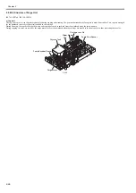
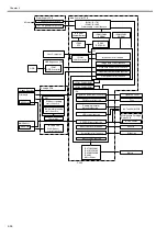
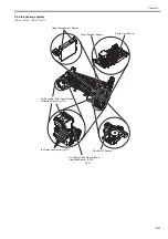
The printer electrical system consists of the main controller PCB and power supply PCB which are mounted on the rear side of the printer, the carriage PCB and
printhead which are mounted in the carriage, and other electrical components such as the operation panel, sensors, and motors.
The main controller PCB manages the image data processing and the entire electrical system, and controls relay PCBs and driver functions.
F-2-30
Power Supply
Main Controller PCB
Operation Panel PCB
Carriage PCB
Содержание iPF750 series
Страница 1: ...Jul 25 2012 Service Manual iPF760 750 series ...
Страница 2: ......
Страница 6: ......
Страница 11: ...Chapter 1 PRODUCT DESCRIPTION ...
Страница 12: ......
Страница 14: ...Contents 1 7 3 5 Self diagnostic Feature 1 71 1 7 3 6 Disposing of the Lithium Battery 1 72 ...
Страница 87: ...Chapter 2 TECHNICAL REFERENCE ...
Страница 88: ......
Страница 99: ...Chapter 2 2 9 ...
Страница 145: ...Chapter 3 INSTALLATION ...
Страница 146: ......
Страница 148: ......
Страница 152: ......
Страница 153: ...Chapter 4 DISASSEMBLY REASSEMBLY ...
Страница 154: ......
Страница 156: ......
Страница 214: ...Chapter 4 4 58 2 Shaft Cleaner 1 F 4 119 1 ...
Страница 215: ...Chapter 4 4 59 3 Upper Cover Hinge Catch 1 Roll Cover Slide Guide 2 F 4 120 2 1 ...
Страница 218: ......
Страница 219: ...Chapter 5 MAINTENANCE ...
Страница 220: ......
Страница 222: ......
Страница 227: ...Chapter 5 5 5 ...
Страница 228: ......
Страница 229: ...Chapter 6 TROUBLESHOOTING ...
Страница 230: ......
Страница 232: ......
Страница 250: ......
Страница 251: ...Chapter 7 SERVICE MODE ...
Страница 252: ......
Страница 254: ......
Страница 305: ......
Страница 306: ......
Страница 307: ...Chapter 8 ERROR CODE ...
Страница 308: ......
Страница 310: ......
Страница 327: ...Jul 25 2012 ...
Страница 328: ......


