


Jam Code
Jam Type
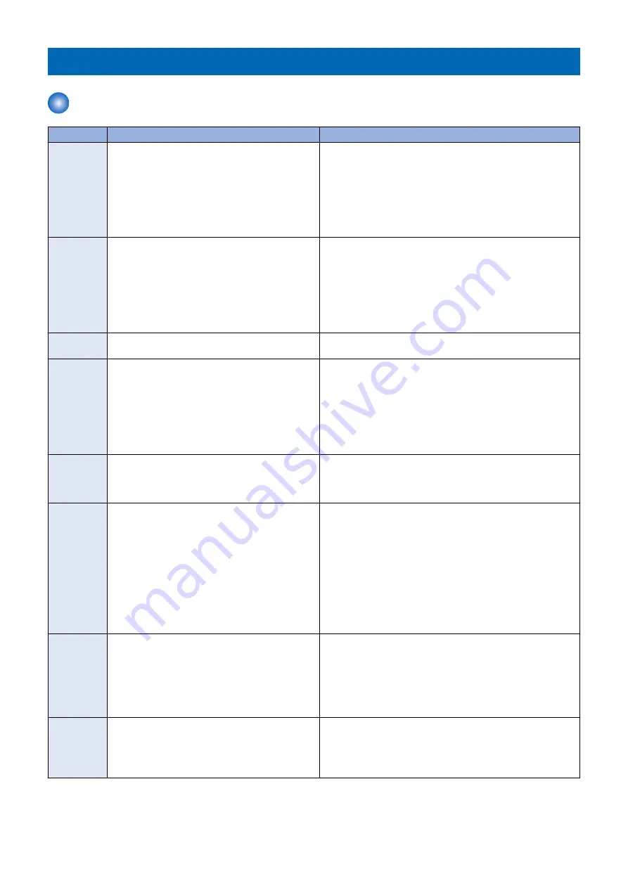
Type
Overview of detection
Check items (in arbitrary order)
Delay
A delay jam occurs when a sensor was not turned ON
although a specified period of time had passed after
the start of detection by the sensor.
• Remaining paper at the upstream of the target sensor
• Soiling on the target sensor
• Displacement of the target sensor position
• Failure of the target sensor
• Soiling (grease)/deterioration/failure of a drive motor located
upstream of the target sensor
• Soiling (paper dust)/deterioration/failure of a drive roller lo-
cated upstream of the target sensor
Stationary
A stationary jam occurs when a sensor was not turned
OFF although a specified period of time had passed
after the sensor was turned ON.
• Remaining paper near the target sensor
• Soiling on the target sensor
• Displacement of the target sensor position
• Failure of the target sensor
• Soiling (grease)/deterioration/failure of a drive motor located
upstream of the target sensor
• Soiling (paper dust)/deterioration/failure of a drive roller lo-
cated upstream of the target sensor
Door open
A door open jam occurs when a sensor detected door
open during printing operation.
• Door open during printing
Sequence
A sequence jam occurs when there was an error in
sensor detection signal at printing operation se-
quence.
Since the jam may occur due to sporadic noise with
software of each equipment or communication line
(interruption of communication), failure of the part is
not the cause of the jam. After the jam is removed, the
machine works.
• Opening/closing of the door
• Turning OFF and then ON the power
• Error near the target sensor (soiling/displacement/failure of
the sensor, error in harness/open circuit of harness, soiling
(grease)/deterioration/failure of a drive motor, or soiling (pa-
per dust)/deterioration/failure of a drive roller)
Power-on
A power-on jam occurs when a sensor detected ON
state at power-on.
• Remaining paper in the machine
• Soiling on the target sensor
• Failure of the target sensor
• Foreign matter on the target sensor (paper dust, paper lint)
Error avoid-
ance
An error avoidance jam occurs when an error in the
machine (excluding parts failure) was detected.
Printing operation is suspended to avoid error occur-
rence by error code; therefore, parts failure is not the
cause of the jam.
After the jam is removed, the machine works.
If it is due to parts failure, an error code instead of the
error avoidance jam is displayed on UI and printing
operation is suspended. In such case, service tech-
nician should perform remedial work for the error
code.
• Opening/closing of the door after jam removal
• Turning OFF and then ON the power after jam removal
Size error
A size error jam occurs when the difference between
the paper length detected by the Cassette Guide
Plate/specified on the Control Panel and the length
measured by the Registration Sensor is out of the
specified range.
• Difference in paper size
• Wrong paper size setting
• Error in the Document Size Sensor (soiling/displacement/
failure of the sensor)
• Error in the Paper Size Detection Unit (failure of mechanical
structure for size detection, failure of the Guide Plate, or fail-
ure of the Cassette Size Switch)
Different me-
dia
A different media jam occurs when the paper type
specified from a PC or the Control Panel differed from
the one detected by the sensor.
• Difference in paper type
• Wrong paper type setting
• Error in the Transparency Sensor (soiling/displacement/fail-
ure of the sensor)
• Soiling on the Reflection Plate of the Transparency Sensor
7. Error/Jam/Alarm
617
Содержание imageRUNNER ADVANCE C3330 Series
Страница 1: ...Revision 7 0 imageRUNNER ADVANCE C3330 C3325 C3320 Series Service Manual ...
Страница 18: ...Product Overview 1 Product Lineup 7 Features 11 Specifications 17 Parts Name 26 ...
Страница 278: ...J1335 J1066 J1022 J1146 J1050 J1051 J130 J1052 J1053 J1333 J120 J128 J130 4 Parts Replacement and Cleaning 266 ...
Страница 326: ...CAUTION Check that the color of the seal at the center is black 4 Parts Replacement and Cleaning 314 ...
Страница 359: ...6 Remove the Bottle Drive Unit 1 2 Bosses 2 5 Hooks 3 2 2 3 3 3 2 2 1 3 3 3 3 4 Parts Replacement and Cleaning 347 ...
Страница 399: ...Adjustment 5 Pickup Feed System 388 Document Exposure System 391 Actions after Replacement 393 ...
Страница 518: ...Error Jam Alarm 7 Overview 507 Error Code 511 Jam Code 617 Alarm Code 624 ...
Страница 1020: ...9 Installation 1008 ...
Страница 1022: ...2 Perform steps 3 to 5 in each cassette 9 Installation 1010 ...
Страница 1024: ...5 6 Checking the Contents Cassette Feeding Unit 1x 3x 2x 1x 9 Installation 1012 ...
Страница 1027: ...3 4 NOTE The removed cover will be used in step 6 5 2x 2x 9 Installation 1015 ...
Страница 1046: ...When the Kit Is Not Used 1 2 Close the Cassette 2 When the Kit Is Used 1 9 Installation 1034 ...
Страница 1058: ...3 4 CAUTION Be sure that the Inner 2 way Tray Support Member is installed properly 9 Installation 1046 ...
Страница 1062: ...Installation procedure 1 NOTE The work is the same when the Utility Tray is installed 9 Installation 1050 ...
Страница 1068: ... Removing the Covers 1 2x 2 1x 9 Installation 1056 ...
Страница 1070: ...3 1x 1x 9 Installation 1058 ...
Страница 1080: ...Installation Outline Drawing Installation Procedure 1 Remove the all tapes from this equipment 2 2x 9 Installation 1068 ...
Страница 1081: ...3 CAUTION To avoid damage do not pull the A part of the Utility Tray too much A 4 9 Installation 1069 ...
Страница 1083: ...6 7 TP M4x8 2x 2x 9 Installation 1071 ...
Страница 1084: ...When Installing the USB Keyboard 1 Cap Cover Wire Saddle 9 Installation 1072 ...
Страница 1095: ...9 2x 10 2x 11 Remove the Face Seals from the Reader Right Cover The removed Face Seals will not be used 9 Installation 1083 ...
Страница 1101: ... When Stopping to Use 1 Press Reset key or the Voice Recognition button for more than 3 seconds 9 Installation 1089 ...
Страница 1129: ...9 2x 10 2x 11 9 Installation 1117 ...
Страница 1135: ...Remove the covers 1 ws 2x 2 1x 9 Installation 1123 ...
Страница 1140: ...2 2x 3 Connect the power plug to the outlet 4 Turn ON the power switch 9 Installation 1128 ...
Страница 1155: ...Installation Outline Drawing Installation Procedure Removing the Covers 1 2x 2 1x 9 Installation 1143 ...
Страница 1157: ...3 Connect Power Cable and Signal Cable disconnected in the step 2 to the Encryption Board 2 Connectors 2x 9 Installation 1145 ...
Страница 1167: ...Installation Procedure Removing the Covers 1 2x 2 1x 3 2x Installing the Removable HDD Kit 9 Installation 1155 ...
Страница 1176: ... A 2x Installing the Covers 1 1x 2 2x 9 Installation 1164 ...
Страница 1177: ...3 4 2x Installing the Removable HDD 1 Install the HDD Unit to the HDD Slot 9 Installation 1165 ...
Страница 1182: ...Installation Outline Drawing Installation Procedure Removing the Covers 1 2x 2 1x 9 Installation 1170 ...
Страница 1190: ...14 Install the Cable Guide to the HDD Frame 4 Hooks 1 Boss 9 Installation 1178 ...
Страница 1195: ...23 Secure the Power Cable in place using the Wire Saddle 1x Installing the Covers 1 1x 2 2x 9 Installation 1183 ...
Страница 1196: ...3 4 2x Installing the Removable HDD 1 Install the HDD Unit to the HDD Slot 9 Installation 1184 ...


