


3. Transmission of the data of changes made in service mode menu settings is not performed instantly, but performed when a
specified period of 60 minutes elapse after the change of service mode menu settings is detected or when a communication
test is performed at the time of power-on. (There is a time lag.)
4. When service mode menu settings (COPIER > Adjust) are made, transmission is performed even when no change is made
in the target data to be transmitted.
Transmission of service mode data is also performed when changes are made in the service mode setting value not subject
to transmission (items other than Level 1, 2) or when settlement of a value is performed without changing the setting value.
Service cautions
1. After clearing RAM of the Main Controller PCB, initialization of the E-RDS setting (ERDS-DAT) and a communication test
(COM-TEST) need to be performed.
Failure to do so will result that the counter transmitting value to the UGW may become unusual.
Also, after replacing the main controller board, all settings must be reprogrammed.
2. The following settings in service mode must not be change unless there are specific instructions to do so. Changing these
values will cause error in communication with UGW.
• Set port number of UGW
SERVICE MODE > COPIER > Function > INSTALL > RGW-PORT
Default : 443
• URL setting of UGW
SERVICE MODE > COPIER > Function > INSTALL > RGW-ADR
Default : https://a01.ugwdevice.net/ugw/agentif010
3. If the e-Maintenance/ imageWARE Remote contract of the device is invalid, be sure to turn OFF the E-RDS setting (E-RDS :
0).
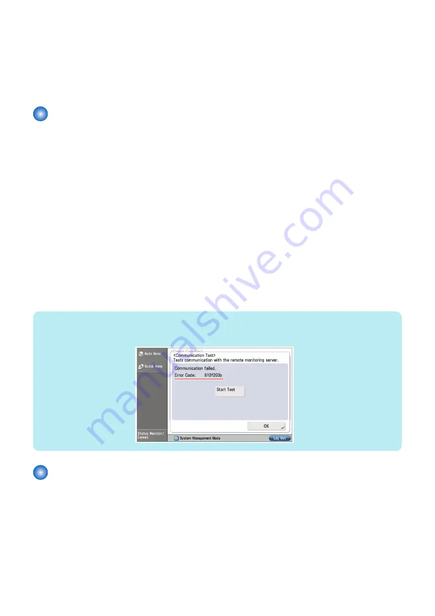
4. With this machine, a communication test can be conducted from the [Counter Check] on the Control Panel.* When conducting
a communication test from the [Counter Check] on the Control Panel, pay attention on the following points:
• During a communication test, do not take any actions such as pressing a key. Actions are not accepted until the
communication test is completed (actions are ignored).
• When a communication test is being conducted from service mode or from the [Counter Check] on the Control Panel,
do not conduct a communication test from the other. These operations are not guaranteed.
NOTE:
*The user can conduct a communication test and seen the communication test result.
If the communication results in failure, an error code (a hexadecimal number, 8 digits) appears on the touch panel display.
E-RDS Setup
■ Confirmation and preparation in advance
To monitor this machine with e-Maintenance/ imageWARE Remote, the following settings are required.
● Advance preparations
The following network-related information needs to be obtained from the user's system administrator in advance.
Information item 1
IP address settings
• Automatic setting : DHCP, RARP, BOOTP
2. Technology
187
Содержание imageRUNNER ADVANCE C3330 Series
Страница 1: ...Revision 7 0 imageRUNNER ADVANCE C3330 C3325 C3320 Series Service Manual ...
Страница 18: ...Product Overview 1 Product Lineup 7 Features 11 Specifications 17 Parts Name 26 ...
Страница 278: ...J1335 J1066 J1022 J1146 J1050 J1051 J130 J1052 J1053 J1333 J120 J128 J130 4 Parts Replacement and Cleaning 266 ...
Страница 326: ...CAUTION Check that the color of the seal at the center is black 4 Parts Replacement and Cleaning 314 ...
Страница 359: ...6 Remove the Bottle Drive Unit 1 2 Bosses 2 5 Hooks 3 2 2 3 3 3 2 2 1 3 3 3 3 4 Parts Replacement and Cleaning 347 ...
Страница 399: ...Adjustment 5 Pickup Feed System 388 Document Exposure System 391 Actions after Replacement 393 ...
Страница 518: ...Error Jam Alarm 7 Overview 507 Error Code 511 Jam Code 617 Alarm Code 624 ...
Страница 1020: ...9 Installation 1008 ...
Страница 1022: ...2 Perform steps 3 to 5 in each cassette 9 Installation 1010 ...
Страница 1024: ...5 6 Checking the Contents Cassette Feeding Unit 1x 3x 2x 1x 9 Installation 1012 ...
Страница 1027: ...3 4 NOTE The removed cover will be used in step 6 5 2x 2x 9 Installation 1015 ...
Страница 1046: ...When the Kit Is Not Used 1 2 Close the Cassette 2 When the Kit Is Used 1 9 Installation 1034 ...
Страница 1058: ...3 4 CAUTION Be sure that the Inner 2 way Tray Support Member is installed properly 9 Installation 1046 ...
Страница 1062: ...Installation procedure 1 NOTE The work is the same when the Utility Tray is installed 9 Installation 1050 ...
Страница 1068: ... Removing the Covers 1 2x 2 1x 9 Installation 1056 ...
Страница 1070: ...3 1x 1x 9 Installation 1058 ...
Страница 1080: ...Installation Outline Drawing Installation Procedure 1 Remove the all tapes from this equipment 2 2x 9 Installation 1068 ...
Страница 1081: ...3 CAUTION To avoid damage do not pull the A part of the Utility Tray too much A 4 9 Installation 1069 ...
Страница 1083: ...6 7 TP M4x8 2x 2x 9 Installation 1071 ...
Страница 1084: ...When Installing the USB Keyboard 1 Cap Cover Wire Saddle 9 Installation 1072 ...
Страница 1095: ...9 2x 10 2x 11 Remove the Face Seals from the Reader Right Cover The removed Face Seals will not be used 9 Installation 1083 ...
Страница 1101: ... When Stopping to Use 1 Press Reset key or the Voice Recognition button for more than 3 seconds 9 Installation 1089 ...
Страница 1129: ...9 2x 10 2x 11 9 Installation 1117 ...
Страница 1135: ...Remove the covers 1 ws 2x 2 1x 9 Installation 1123 ...
Страница 1140: ...2 2x 3 Connect the power plug to the outlet 4 Turn ON the power switch 9 Installation 1128 ...
Страница 1155: ...Installation Outline Drawing Installation Procedure Removing the Covers 1 2x 2 1x 9 Installation 1143 ...
Страница 1157: ...3 Connect Power Cable and Signal Cable disconnected in the step 2 to the Encryption Board 2 Connectors 2x 9 Installation 1145 ...
Страница 1167: ...Installation Procedure Removing the Covers 1 2x 2 1x 3 2x Installing the Removable HDD Kit 9 Installation 1155 ...
Страница 1176: ... A 2x Installing the Covers 1 1x 2 2x 9 Installation 1164 ...
Страница 1177: ...3 4 2x Installing the Removable HDD 1 Install the HDD Unit to the HDD Slot 9 Installation 1165 ...
Страница 1182: ...Installation Outline Drawing Installation Procedure Removing the Covers 1 2x 2 1x 9 Installation 1170 ...
Страница 1190: ...14 Install the Cable Guide to the HDD Frame 4 Hooks 1 Boss 9 Installation 1178 ...
Страница 1195: ...23 Secure the Power Cable in place using the Wire Saddle 1x Installing the Covers 1 1x 2 2x 9 Installation 1183 ...
Страница 1196: ...3 4 2x Installing the Removable HDD 1 Install the HDD Unit to the HDD Slot 9 Installation 1184 ...


