


The parts counter is automatically cleared, but it is not cleared if the Waste Toner Container is replaced while "preparation warning"
or "full" is not detected or while the power is off.
The parts counter can be manually cleared by executing the following service mode.
COPIER > COUNTER > DRBL-1 > WST-TNR
● Waste Toner Container Detection
Purpose
To detect the presence/absence of the Waste Toner Container
Control description
The Waste Toner Container Detection Switch (SW01) is used to detect the presence/absence of the Waste Toner Container.
SW01
■ Other Controls
● Special Controls
This machine has the following sequences as the special sequence.
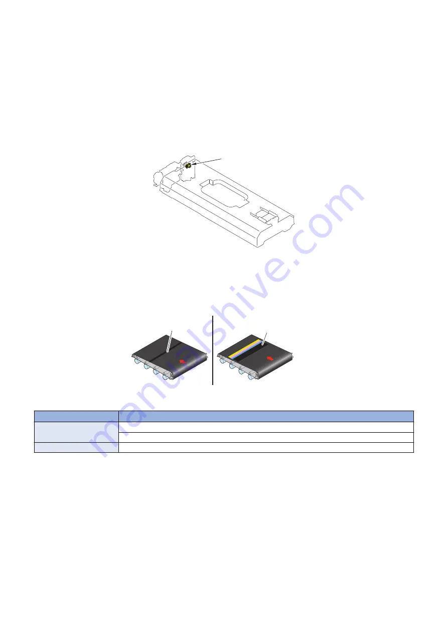
Transparency Sequence
Black Band Sequence
Solid color band (Y/M/C/Bk)
Developing Discharge Sequence
Solid black band
Black Band Sequence
Control timing
Condition
At paper interval
For each 100 accumulated images
When transparency is fed
At job completion
For each 70 accumulated images
If continuous printing is performed without toner being fed to the ITB Cleaning Blade, the Cleaning Blade may flip.
Because of this, toner (solid Bk with the width of 297 mm and the length of 1 mm) is transferred to the ITB and is supplied to the
ITB Cleaning Blade.
Developing discharge sequence
Control timing: When the average image ratio per sheet reaches 2% or less
Developing performance may decrease when performing continuous printing with low image ratio. To prevent this error, an
adequate amount of toner based on the average image ratio for each color (width = A4, length = a solid color band according to
the deteriorated toner amount) is transferred to the ITB.
Related service mode
• Setting of the image ratio for executing the Y-color toner ejection (Lv.2):
COPIER > OPTION > IMG-DEV > DELV-THY
• Setting of the image ratio for executing the M-color toner ejection (Lv.2):
COPIER > OPTION > IMG-DEV > DELV-THM
2. Technology
94
Содержание imageRUNNER ADVANCE C3330 Series
Страница 1: ...Revision 7 0 imageRUNNER ADVANCE C3330 C3325 C3320 Series Service Manual ...
Страница 18: ...Product Overview 1 Product Lineup 7 Features 11 Specifications 17 Parts Name 26 ...
Страница 278: ...J1335 J1066 J1022 J1146 J1050 J1051 J130 J1052 J1053 J1333 J120 J128 J130 4 Parts Replacement and Cleaning 266 ...
Страница 326: ...CAUTION Check that the color of the seal at the center is black 4 Parts Replacement and Cleaning 314 ...
Страница 359: ...6 Remove the Bottle Drive Unit 1 2 Bosses 2 5 Hooks 3 2 2 3 3 3 2 2 1 3 3 3 3 4 Parts Replacement and Cleaning 347 ...
Страница 399: ...Adjustment 5 Pickup Feed System 388 Document Exposure System 391 Actions after Replacement 393 ...
Страница 518: ...Error Jam Alarm 7 Overview 507 Error Code 511 Jam Code 617 Alarm Code 624 ...
Страница 1020: ...9 Installation 1008 ...
Страница 1022: ...2 Perform steps 3 to 5 in each cassette 9 Installation 1010 ...
Страница 1024: ...5 6 Checking the Contents Cassette Feeding Unit 1x 3x 2x 1x 9 Installation 1012 ...
Страница 1027: ...3 4 NOTE The removed cover will be used in step 6 5 2x 2x 9 Installation 1015 ...
Страница 1046: ...When the Kit Is Not Used 1 2 Close the Cassette 2 When the Kit Is Used 1 9 Installation 1034 ...
Страница 1058: ...3 4 CAUTION Be sure that the Inner 2 way Tray Support Member is installed properly 9 Installation 1046 ...
Страница 1062: ...Installation procedure 1 NOTE The work is the same when the Utility Tray is installed 9 Installation 1050 ...
Страница 1068: ... Removing the Covers 1 2x 2 1x 9 Installation 1056 ...
Страница 1070: ...3 1x 1x 9 Installation 1058 ...
Страница 1080: ...Installation Outline Drawing Installation Procedure 1 Remove the all tapes from this equipment 2 2x 9 Installation 1068 ...
Страница 1081: ...3 CAUTION To avoid damage do not pull the A part of the Utility Tray too much A 4 9 Installation 1069 ...
Страница 1083: ...6 7 TP M4x8 2x 2x 9 Installation 1071 ...
Страница 1084: ...When Installing the USB Keyboard 1 Cap Cover Wire Saddle 9 Installation 1072 ...
Страница 1095: ...9 2x 10 2x 11 Remove the Face Seals from the Reader Right Cover The removed Face Seals will not be used 9 Installation 1083 ...
Страница 1101: ... When Stopping to Use 1 Press Reset key or the Voice Recognition button for more than 3 seconds 9 Installation 1089 ...
Страница 1129: ...9 2x 10 2x 11 9 Installation 1117 ...
Страница 1135: ...Remove the covers 1 ws 2x 2 1x 9 Installation 1123 ...
Страница 1140: ...2 2x 3 Connect the power plug to the outlet 4 Turn ON the power switch 9 Installation 1128 ...
Страница 1155: ...Installation Outline Drawing Installation Procedure Removing the Covers 1 2x 2 1x 9 Installation 1143 ...
Страница 1157: ...3 Connect Power Cable and Signal Cable disconnected in the step 2 to the Encryption Board 2 Connectors 2x 9 Installation 1145 ...
Страница 1167: ...Installation Procedure Removing the Covers 1 2x 2 1x 3 2x Installing the Removable HDD Kit 9 Installation 1155 ...
Страница 1176: ... A 2x Installing the Covers 1 1x 2 2x 9 Installation 1164 ...
Страница 1177: ...3 4 2x Installing the Removable HDD 1 Install the HDD Unit to the HDD Slot 9 Installation 1165 ...
Страница 1182: ...Installation Outline Drawing Installation Procedure Removing the Covers 1 2x 2 1x 9 Installation 1170 ...
Страница 1190: ...14 Install the Cable Guide to the HDD Frame 4 Hooks 1 Boss 9 Installation 1178 ...
Страница 1195: ...23 Secure the Power Cable in place using the Wire Saddle 1x Installing the Covers 1 1x 2 2x 9 Installation 1183 ...
Страница 1196: ...3 4 2x Installing the Removable HDD 1 Install the HDD Unit to the HDD Slot 9 Installation 1184 ...


