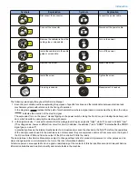


Laser Safety
Since radiation emitted inside the machine is completely confined within protective housings and external covers, the laser beam
cannot escape from the machine during any phase of user operation.
Therefore this machine is classified in Class 1 laser products that are regarded as safe during normal use according to
International Standard IEC60825-1.
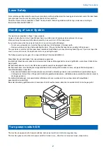
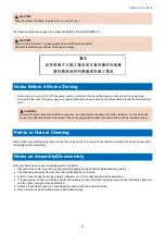
Handling of Laser System
This machine is classified in Class 1 laser products.
However, inside the machine, Class 3B laser beam is emitted and is hazardous when entered into an eye.
When servicing the area around the laser assembly, be sure to turn off the main power.
If you must service while the power is turned on, be sure to keep the followings:
• Do not use a screwdriver or tools that have a high level of reflectance in the laser path.
• Remove watches and rings before starting the work. (They can reflect the laser beam, possibly hitting an eye.)
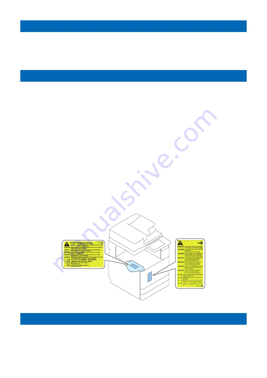
The machine's covers that confine laser beam radiation are identified by means of warning label (Figure). If you must open the
cover, be sure not to enter the laser beam into an eye during the work.
The following warnings are given to comply with Safety Principles (EN60950-1).
Diese Maschine ist der Klasse 1 der Laserprodukte zugeordnet.
Innerhalb der Maschine wird jedoch ein Laserstrahl der Klasse 3B ausgestrahlt und es ist gefährlich, wenn dieser Strahl in die
Augen gerät.
Bei Servicearbeiten am oder in der Nähe des Laserteils zuerst das Hauptgerät abschalten.
Bei Servicearbeiten, die unbedingt bei eingeschaltetem Gerät durchgeführt werden müssen, auf jeden Fall die folgenden
Vorsichtsmaßnahmen beachten.
• Keine stark reflektierenden Schraubenzieher oder ähnliche Werkzeuge direkt in den Lichtpfad des Laserstrahls bringen.
• Vor Beginn der Arbeit Uhren, Ringe und ähnliche Gegenstände abnehmen. (Reflektierende Laserstrahlen könnten sonst in
die Augen geraten.)
Die Geräte-Abdeckungen, die Laserstrahlen reflektieren können, werden durch einen besonderen Warnaufkleber
gekennzeichnet (siehe Bild).
Muss die Abdeckung geöffnet werden, besondere Vorsicht walten lassen, damit der Laserstrahl nicht in die Augen gerät.
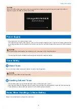
Turn power switch ON
The machine is equipped with 2 power switches: main power switch and control energy saver key.
The machine goes on when the main power switch is turned on (i.e., other than in low power mode, sleep mode).
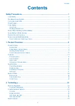
Safety Precautions
2
Содержание imagerunner advance 4551i
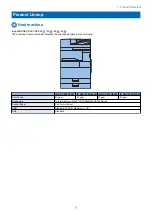
Страница 19: ...Product Overview 1 Product Lineup 7 Features 13 Specifications 16 Name of Parts 26 ...
Страница 155: ...Periodical Service 3 Consumable Parts List 143 Cleaning Check Adjustment Locations 146 ...
Страница 175: ...Switch SW1 SW2 SW4 Symbol Name SW1 Main Switch SW2 Front Door Switch SW4 Environment Switch 4 Disassembly Assembly 162 ...
Страница 244: ...3 Remove the Platen roller unit 1 2 Claws 2 2x 2 1 2 4 Remove the Cover 1 2 Screws 2 2x 2 1 4 Disassembly Assembly 231 ...
Страница 295: ...2 Remove the Multi purpose Tray Pickup Roller Cover 1 1 Screw 2 1x 1 2 4 Disassembly Assembly 282 ...
Страница 392: ...Error Jam Alarm 7 Overview 380 Error Code 383 Jam Code 509 Alarm Code 520 ...
Страница 545: ...Service Mode 8 Overview 533 COPIER 549 FEEDER 845 SORTER 851 BOARD 871 ...
Страница 549: ... i Press the button to display the screen showing the locations of electrical components 8 Service Mode 536 ...
Страница 892: ...Unpacking 1 2 1200 mm 840 mm 769 mm 1230 mm 2430 mm 3 9 Installation 879 ...
Страница 895: ...3 4 NOTE Keep the removed screws for relocating the host machine 2x 5 6 7 9 Installation 882 ...
Страница 896: ...8 9 10 1x Installing the Air Filter 1 9 Installation 883 ...
Страница 897: ...2 3 Installing the Drum Unit 1 2 3 9 Installation 884 ...
Страница 899: ...8 NOTE The screw removed at procedure 4 is used 1x 9 10 11 12 9 Installation 886 ...
Страница 921: ...7 2x 8 2x Binding M4x8 NOTE After completion of the work perform Installing the Equipment 9 Installation 908 ...
Страница 923: ...5 6 NOTE Use the screws and Rubber Caps removed in step 1 2x 7 2x 9 Installation 910 ...
Страница 931: ...5 1x 6 1x 7 1x 1x P Tightening M3x12 8 NOTE Use the part removed in step 3 1x 9 9 Installation 918 ...
Страница 935: ...7 1x 8 9 6x 10 2x 9 Installation 922 ...
Страница 936: ...11 Installing the NFC Kit 1 2 2x 3 TP M3x4 1x 9 Installation 923 ...
Страница 938: ...4 5 1x 6 9 Installation 925 ...
Страница 970: ...38 Close the Front Cover 39 Close the Right Cover 40 Turn the environment Heater Switch ON 9 Installation 957 ...
Страница 985: ...8 2x 2x TP M4x8 Black When installing the USB Keyboard 1 9 Installation 972 ...
Страница 991: ...7 4x 8 1x 1x Lower Cover 9 1x 10 1x 1x 9 Installation 978 ...
Страница 992: ...11 1x 1x 12 1x 13 TP M3x12 2x 14 4x TP M3x6 9 Installation 979 ...
Страница 997: ...Installation Procedure 1 2 2x 3 2x 4 6x 5 4x 9 Installation 984 ...
Страница 998: ...6 7 NOTE Do not close the Wire Saddle 1x 1x 8 9 9 Installation 985 ...
Страница 1000: ...12 NOTE Be sure to adjust the number of cushions according to the thickness of the Card Reader 13 14 15 16 9 Installation 987 ...
Страница 1001: ...17 2x 18 19 Connect the power plug of the host machine to the power outlet 20 Turn the main power switch ON 9 Installation 988 ...
Страница 1003: ...2 1x 1x 3 2x 2x 4 9 Installation 990 ...
Страница 1007: ...13 4x 14 15 2x NOTE The removed screw is used at procedure 17 16 Binding M4x14 Binding M3x14 2x M4x14 M3x14 9 Installation 994 ...
Страница 1008: ...17 NOTE Use the screw removed at procedure 15 2x 18 19 20 NOTE Install both side of the cable 9 Installation 995 ...
Страница 1012: ...2 1x 1x 3 2x 2x 4 9 Installation 999 ...
Страница 1014: ...7 CAUTION The connector must be contacted TP㸹M3x6 3x 1x 8 4x 9 9 Installation 1001 ...
Страница 1016: ...13 4x 14 15 Binding M4x16 Binding M3x16 2x M3x16 M4x16 16 Binding M4x6 1x 9 Installation 1003 ...
Страница 1017: ...17 NOTE Be sure to attach the Ring Cores within 50 mm from the end of the Speaker Cable 50mm 18 2x 19 20 9 Installation 1004 ...
Страница 1023: ...Installation Procedure Preparation 1 4x 2 1x 1x 3 2x 9 Installation 1010 ...
Страница 1026: ...2 4x 3 Connect the power plug of the host machine to the power outlet 4 Turn ON the main power switch 9 Installation 1013 ...
Страница 1029: ...4 5 1x 1x 9 Installation 1016 ...
Страница 1044: ...6 7 8 9 Be sure to request the user to padlock the removable HDD to discourage theft 10 4x 11 9 Installation 1031 ...
Страница 1048: ...3 2x TP M3x8 Black 4 2x TP M3x6 5 9 Installation 1035 ...
Страница 1053: ... Installing the Removable HDD Kit 1 2x 2x 2 3 1x 4 9 Installation 1040 ...
Страница 1065: ...3 2x TP M3x8 Black 4 2x TP M3x6 5 9 Installation 1052 ...
Страница 1071: ... Installing the Removable HDD Kit 1 2x 2x 2 3 1x 4 9 Installation 1058 ...


