


Host machine_10/18
A
C
B
D
E
F
A
C
B
D
E
F
4
3
2
7
6
5
1
8
4
3
2
7
6
5
1
8
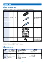
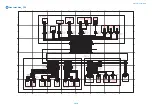
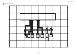
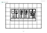
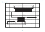
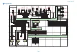
UN18
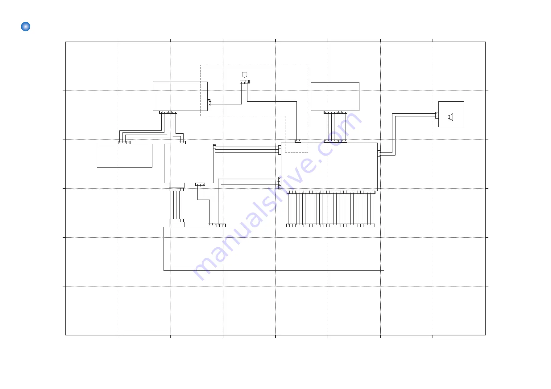
G3 2nd Line FAX PCB
UN19
Modular PCB (2 to 4 lines)
UN70
G3 3rd/4th Line FAX PCB
3 4 5
1 2
J708
(J4013)
N
.C
.
G
N
D
+12S_U
I_F
AX
G
N
D
+5C
_F
AX
+12S_U
I_F
AX
(J4012)
EXB_
AD
D
R
2
EXB_
D
T
0
EXB_
D
T
1
EXB_
AD
D
R
3
EXB_
D
T
2
EXB_
AD
D
R
4
EXB_
D
T
3
EXB_
AD
D
R
5
G
N
D
EXB_
AD
D
R
1
G
N
D
(J4011)
EXB_
AD
D
R
8
#
R
ESET
_
F
AX
#
EXB_
C
S1
#
EXB_
WE
#
EXB_
O
E
EXB_
D
T
7
#
F
O
F
F
H
K
#
F
C
ID
G
N
D
EXB_
D
T
5
EXB_
AD
D
R
6
EXB_
D
T
4
EXB_
AD
D
R
7
EXB_
D
T
6
G
N
D
#
IN
T
_
F
AX
+3
.3
R
#
F
C
ID
_
U
SB
#
MO
D
EM_
SN
S
G
N
D
3 4 5
1 2
G
N
D
SET_R
ST_F
AX_N
+3.3R
_F
AX
U
SBF
AX_D
N
U
SBF
AX_D
P
N.
C.
(J2)
(J1)
(J403)
(MiniUSB)
(J5)
N.C.
(J2)
2
_
L
IN
E_
L
2
2
_
L
IN
E_
L
1
3
_
L
IN
E_
L
1
3
_
L
IN
E_
L
2
4
_
L
IN
E_
L
1
4
_
L
IN
E_
L
2
(J2)
(J8)
(J6)
MONI_USB
GND
#FC_USB_IN
N.
C.
(J7)
(J3)
(J4)
(J4)
N.C
(J1)
T2
T1
N.
C
N.
C
L1
CT2
CT1
L2
GND
SP_OUT
(J2)
BL
BL
3
4
5
6
1
2
J704
1 2 3 4 5 6 7 8 9 10111213141516171819202122232425262728293031
J701
1
2
3
4
5
6
7
8
9
10
11
12
13
14
15
16
17
18
19
20
21
22
23
24
25
26
27
28
29
30
31
2
3
4
1
2 3
1
J742
J24
J1
7
2
3
4
1
J26
2 1
J30
1
2
3
J35
J36
1
2
3
2
1
J772
8
1 2 3 4 5 6 7
J733
1
2
J3
1
4
0
D
3 4 5 6
1 2
J775
2
1
8
1 2 3 4 5 6 7
J771
1
2
J751
2
1
J773
2
3
1
J804F
From P.1
E-4
Only for JP
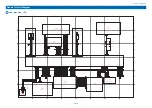
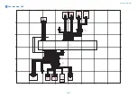
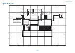
UN14
Riser PCB
UN15
G3 FAX PCB
UN20
Modular PCB (1 line)
SP1
FAX Speaker
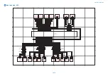
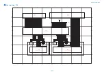
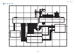
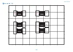
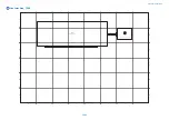
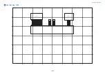
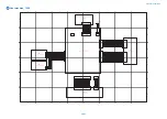
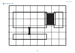
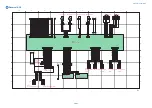
General Circuit Diagram
1081
Содержание imagerunner advance 4551i
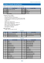
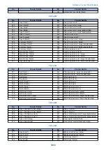
Страница 19: ...Product Overview 1 Product Lineup 7 Features 13 Specifications 16 Name of Parts 26 ...
Страница 155: ...Periodical Service 3 Consumable Parts List 143 Cleaning Check Adjustment Locations 146 ...
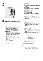
Страница 175: ...Switch SW1 SW2 SW4 Symbol Name SW1 Main Switch SW2 Front Door Switch SW4 Environment Switch 4 Disassembly Assembly 162 ...
Страница 244: ...3 Remove the Platen roller unit 1 2 Claws 2 2x 2 1 2 4 Remove the Cover 1 2 Screws 2 2x 2 1 4 Disassembly Assembly 231 ...
Страница 295: ...2 Remove the Multi purpose Tray Pickup Roller Cover 1 1 Screw 2 1x 1 2 4 Disassembly Assembly 282 ...
Страница 392: ...Error Jam Alarm 7 Overview 380 Error Code 383 Jam Code 509 Alarm Code 520 ...
Страница 545: ...Service Mode 8 Overview 533 COPIER 549 FEEDER 845 SORTER 851 BOARD 871 ...
Страница 549: ... i Press the button to display the screen showing the locations of electrical components 8 Service Mode 536 ...
Страница 892: ...Unpacking 1 2 1200 mm 840 mm 769 mm 1230 mm 2430 mm 3 9 Installation 879 ...
Страница 895: ...3 4 NOTE Keep the removed screws for relocating the host machine 2x 5 6 7 9 Installation 882 ...
Страница 896: ...8 9 10 1x Installing the Air Filter 1 9 Installation 883 ...
Страница 897: ...2 3 Installing the Drum Unit 1 2 3 9 Installation 884 ...
Страница 899: ...8 NOTE The screw removed at procedure 4 is used 1x 9 10 11 12 9 Installation 886 ...
Страница 921: ...7 2x 8 2x Binding M4x8 NOTE After completion of the work perform Installing the Equipment 9 Installation 908 ...
Страница 923: ...5 6 NOTE Use the screws and Rubber Caps removed in step 1 2x 7 2x 9 Installation 910 ...
Страница 931: ...5 1x 6 1x 7 1x 1x P Tightening M3x12 8 NOTE Use the part removed in step 3 1x 9 9 Installation 918 ...
Страница 935: ...7 1x 8 9 6x 10 2x 9 Installation 922 ...
Страница 936: ...11 Installing the NFC Kit 1 2 2x 3 TP M3x4 1x 9 Installation 923 ...
Страница 938: ...4 5 1x 6 9 Installation 925 ...
Страница 970: ...38 Close the Front Cover 39 Close the Right Cover 40 Turn the environment Heater Switch ON 9 Installation 957 ...
Страница 985: ...8 2x 2x TP M4x8 Black When installing the USB Keyboard 1 9 Installation 972 ...
Страница 991: ...7 4x 8 1x 1x Lower Cover 9 1x 10 1x 1x 9 Installation 978 ...
Страница 992: ...11 1x 1x 12 1x 13 TP M3x12 2x 14 4x TP M3x6 9 Installation 979 ...
Страница 997: ...Installation Procedure 1 2 2x 3 2x 4 6x 5 4x 9 Installation 984 ...
Страница 998: ...6 7 NOTE Do not close the Wire Saddle 1x 1x 8 9 9 Installation 985 ...
Страница 1000: ...12 NOTE Be sure to adjust the number of cushions according to the thickness of the Card Reader 13 14 15 16 9 Installation 987 ...
Страница 1001: ...17 2x 18 19 Connect the power plug of the host machine to the power outlet 20 Turn the main power switch ON 9 Installation 988 ...
Страница 1003: ...2 1x 1x 3 2x 2x 4 9 Installation 990 ...
Страница 1007: ...13 4x 14 15 2x NOTE The removed screw is used at procedure 17 16 Binding M4x14 Binding M3x14 2x M4x14 M3x14 9 Installation 994 ...
Страница 1008: ...17 NOTE Use the screw removed at procedure 15 2x 18 19 20 NOTE Install both side of the cable 9 Installation 995 ...
Страница 1012: ...2 1x 1x 3 2x 2x 4 9 Installation 999 ...
Страница 1014: ...7 CAUTION The connector must be contacted TP㸹M3x6 3x 1x 8 4x 9 9 Installation 1001 ...
Страница 1016: ...13 4x 14 15 Binding M4x16 Binding M3x16 2x M3x16 M4x16 16 Binding M4x6 1x 9 Installation 1003 ...
Страница 1017: ...17 NOTE Be sure to attach the Ring Cores within 50 mm from the end of the Speaker Cable 50mm 18 2x 19 20 9 Installation 1004 ...
Страница 1023: ...Installation Procedure Preparation 1 4x 2 1x 1x 3 2x 9 Installation 1010 ...
Страница 1026: ...2 4x 3 Connect the power plug of the host machine to the power outlet 4 Turn ON the main power switch 9 Installation 1013 ...
Страница 1029: ...4 5 1x 1x 9 Installation 1016 ...
Страница 1044: ...6 7 8 9 Be sure to request the user to padlock the removable HDD to discourage theft 10 4x 11 9 Installation 1031 ...
Страница 1048: ...3 2x TP M3x8 Black 4 2x TP M3x6 5 9 Installation 1035 ...
Страница 1053: ... Installing the Removable HDD Kit 1 2x 2x 2 3 1x 4 9 Installation 1040 ...
Страница 1065: ...3 2x TP M3x8 Black 4 2x TP M3x6 5 9 Installation 1052 ...
Страница 1071: ... Installing the Removable HDD Kit 1 2x 2x 2 3 1x 4 9 Installation 1058 ...


