COPYRIGHT © 1999 CANON INC. CANON imageRUNNER 400/330 REV.0 JAN. 1999 PRINTED IN JAPAN (IMPRIME AU JAPON)
9-11
CHAPTER 9 FIXING SYSTEM
Overheating
detection
circuit
230
˚C
Timer circuit
Hard relay off signal 1
(main thermistor error signal)
Overheating/
open detection
circuit
245
˚C
Timer circuit
Hard relay off signal 2
(sub thermistor error signal)
Main Thermistor Overheating Detection Block Diagram
Sub Thermistor Overheating/Open Cir cuit Detection Block Diagram
Phase signal
Open circuit detection: L
Overheating detection: H
To DC-CPU
To DC-CPU
To DC-CPU
To DC-CPU
Image
processor
PCB
Fixing temperature
control
J114
-A7
J113-B1
J114
-A9
J114
-A10
SSR Short Circuit Detection Block Diagram
Main heater
activation
detection
circuit
Sub heater
activation
detection
circuit
Timer circuit
Hard relay off signal 3
(SSR error signal)
H2-D
H1-D
J114-B13
J114-B12
J114-B11
J114-B14
H1-ERR
H2-ERR
Main heater ON: H
to DC-CPU
Sub heater ON: H
to DC-CPU
Fixing
relay
drive
circuit
DC-
CPU
TH1
TH2
SSR
To DC-PC
DC controller circuit
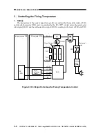
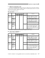
Figure 9-104 Error Monitoring Block of the Fixing Heater
Содержание imageRunner 330
Страница 434: ...COPYRIGHT 1999 CANON INC CANON imageRUNNER 400 330 REV 0 JAN 1999 PRINTED IN JAPAN IMPRIME AU JAPON 14 35 ...
Страница 648: ...APPENDIX A 6 COPYRIGHT 1999 CANON INC CANON imageRUNNER 400 330 REV 0 JAN 1999 PRINTED IN JAPAN IMPRIME AU JAPON ...
Страница 656: ...A 14 COPYRIGHT 1999 CANON INC CANON imageRUNNER 400 330 REV 0 JAN 1999 PRINTED IN JAPAN IMPRIME AU JAPON ...
Страница 660: ...0996S9 9 1 PRINTED IN JAPAN IMPRIME AU JAPON This publication is printed on 70 reprocessed paper ...

