CHAPTER 7 PICK-UP/FEEDING SYSTEM
7-66
COPYRIGHT © 1999 CANON INC. CANON imageRUNNER 400/330 REV.0 JAN. 1999 PRINTED IN JAPAN (IMPRIME AU JAPON)
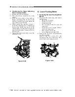
4. Positioning the Paper Deflecting
Plate 1 Solenoid (SL5)
1) Remove the delivery assembly.
2) Place the delivery assembly on a desk
upright.
3) Push down the shaft of the delivery
flapper protruding from the hole in the
delivery assembly front plate against the
edge of the edge of the hole.
4) While keeping the condition in step 3),
loosen the adjusting screw so that the gap
between the rubber ring moved to the
solenoid frame and the steel E-ring of the
paper deflecting plate 1 solenoid (SL5) is
about 0.2 mm.
5) Mount the delivery assembly to end the
adjustment work.
Figure 7-249
G. Lower Feeding Motor
1. Removing the lower Feeding Motor
Mount
1) Disconnect the power plug, and remove
the following:
Rear cover (4 screws)
Flywheel (3 screws)
Connector mount
DC controller PCB (2 screws, all
connectors)
Composite power supply PCB (2
screws, all connectors)
Power supply cord mount
Low-voltage power supply PCB
2) Remove the [3] screws, and detach the
two harness guides.
Remove the four screws [2], and
disconnect the two connectors; then,
detach the lower feeding motor [1].
Figure 7-250
0.2mm
[1]
[1]
[2]
[2]
[3]
Содержание imageRunner 330
Страница 434: ...COPYRIGHT 1999 CANON INC CANON imageRUNNER 400 330 REV 0 JAN 1999 PRINTED IN JAPAN IMPRIME AU JAPON 14 35 ...
Страница 648: ...APPENDIX A 6 COPYRIGHT 1999 CANON INC CANON imageRUNNER 400 330 REV 0 JAN 1999 PRINTED IN JAPAN IMPRIME AU JAPON ...
Страница 656: ...A 14 COPYRIGHT 1999 CANON INC CANON imageRUNNER 400 330 REV 0 JAN 1999 PRINTED IN JAPAN IMPRIME AU JAPON ...
Страница 660: ...0996S9 9 1 PRINTED IN JAPAN IMPRIME AU JAPON This publication is printed on 70 reprocessed paper ...

