Chapter 2
2-31
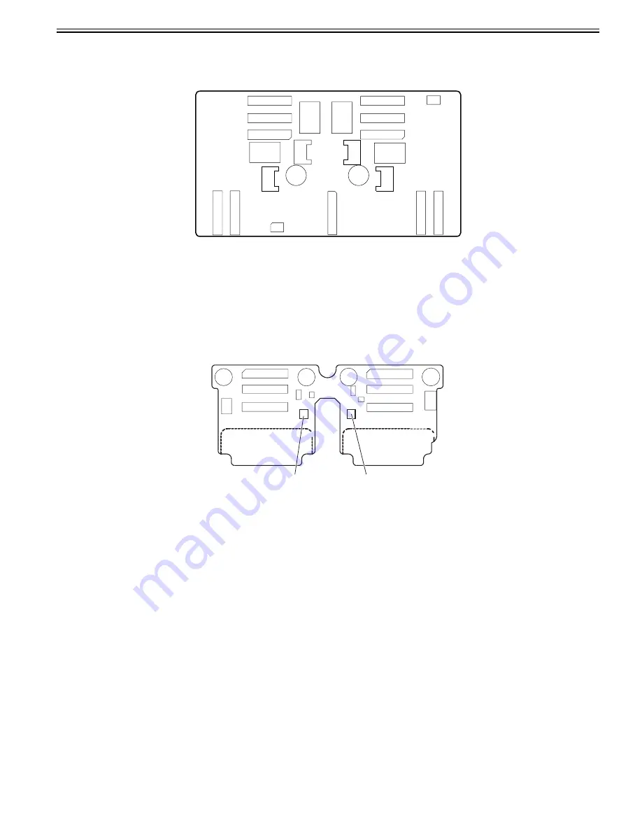
2.4.3 Carriage Relay PCB
2.4.3.1 Carriage relay PCB components
0012-6406
F-2-26
a) Image data relay function
This function relays the image data from the main controller PCB to the printhead.
The function for processing image data is not supported.
b) Sensor relay function
This function relays the input signals from the multi sensor, lift cam sensor, carriage cover sensor, and linear encoder to the main controller PCB.
2.4.4 Head Relay PCB
2.4.4.1 Head relay PCB components
0017-8321
F-2-27
a) Latch IC (IC301,IC304)
DI sensor read control function
Obtains reading value of the DI sensor in the printhead and the head rank value for each color and outputs them to the main controller based on the control commands
from the main controller.
Environment temperature read control function
Outputs the environment temperature detected by the thermistor on the head relay PCB to the main controller based on the control commands from the main con-
troller.
Relay function of the power to the logic components in the printhead
Supplies the power to the logic components in the printhead based on the control commands from the main controller.
b) Multi sensor control IC
These IC's generates the LED control signals and makes gain adjustment for the multi sensor.
c) Image data relay function
This function relays the image data from the main controller PCB to the printhead.
d) Sensor relay function
This function relays the input signals from the multi sensor, lift cam sensor, carriage cover sensor, and linear encoder to the main controller PCB.
IC301
IC304
Содержание imagePROGRAF iPF8400
Страница 2: ......
Страница 6: ......
Страница 11: ...Chapter 1 PRODUCT DESCRIPTION ...
Страница 12: ......
Страница 14: ......
Страница 52: ...Chapter 1 1 38 3 Push in the left and right Basket Rods toward the back all the way until they stop F 1 36 ...
Страница 63: ...Chapter 2 TECHNICAL REFERENCE ...
Страница 64: ......
Страница 106: ......
Страница 107: ...Chapter 3 INSTALLATION ...
Страница 108: ......
Страница 110: ......
Страница 123: ...Chapter 3 3 13 F 3 22 6 FAN UNIT A ...
Страница 125: ...Chapter 3 3 15 ...
Страница 126: ......
Страница 127: ...Chapter 4 DISASSEMBLY REASSEMBLY ...
Страница 128: ......
Страница 130: ......
Страница 165: ...Chapter 4 4 35 5 Upper cover stay shaft hole 1 gear shaft 2 shaft end 3 gear tooth face 4 F 4 54 1 2 4 3 ...
Страница 167: ...Chapter 4 4 37 ...
Страница 168: ......
Страница 169: ...Chapter 5 MAINTENANCE ...
Страница 170: ......
Страница 172: ......
Страница 177: ...Chapter 6 TROUBLESHOOTING ...
Страница 178: ......
Страница 180: ......
Страница 214: ......
Страница 215: ...Chapter 7 SERVICE MODE ...
Страница 216: ......
Страница 218: ......
Страница 273: ...Chapter 7 7 55 ...
Страница 274: ......
Страница 275: ...Chapter 8 ERROR CODE ...
Страница 276: ......
Страница 278: ......
Страница 296: ......
Страница 297: ...Appendix ...
Страница 298: ......
Страница 307: ...Sep 14 2012 ...
Страница 308: ......


