Chapter 7
7-3
7.1.3 Electrostatic Latent Image Formation Block
0019-5014
imageCLASS MF9170c / imageCLASS MF9150c / imageCLASS MF8450c
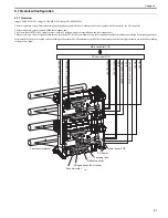
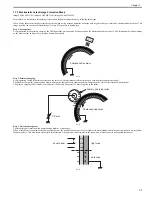
In this block, an electrostatic latent image is formed on the photosensitive drum by following three steps.
When a laser beam scans the photosensitive drum charged with a negative potential, an image with negative charge is formed on the photosensitive drum. This
image is called "an electrostatic latent image" because it is invisible to human eyes.
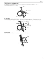
Step 1: Pre-exposure
As a preparation for the primary charging, the LED light of the pre-exposure LED is exposed on the photosensitive drum surface. This eliminates the residual charge
on the drum surface in order to avoid image density unevenness.
F-7-3
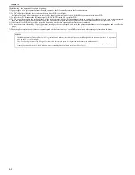
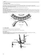
Step 2: Primary charging
As a preparation for the latent image formation, the surface of the photosensitive drum is changed with a uniform negative potential.
The machine charges the photosensitive drum with negative charge directly from the primary charging roller, which is interlocked with the drum.
The primary charging roller is made of a conductive rubber, and a negative DC bias is applied to the roller.
F-7-4
Step 3: Laser beam exposure
The latent image is formed on the photosensitive drum by a laser beam.
When a laser beam is exposed on the photosensitive drum, the potential on the exposed area (light area) is neutralized and the negative potential is removed from
the drum surface. This area forms electrostatic latent images. A negative potential remains in the area where a laser beam was not exposed (dark area).
F-7-5
Photosensitive drum
LED
Photosensitive drum
Primary charging roller
DC bias
Laser beam
dark area
light area
Содержание imageCLASS MF8450c
Страница 16: ...Chapter 1 Introduction ...
Страница 55: ...Chapter 2 Basic Operation ...
Страница 61: ...Chapter 3 Main Controller ...
Страница 75: ...Chapter 4 Original Exposure System ...
Страница 88: ...Chapter 5 Original Feeding System ...
Страница 105: ...Chapter 6 Laser Exposure ...
Страница 113: ...Chapter 7 Image Formation ...
Страница 150: ...Chapter 8 Pickup and Feed System ...
Страница 184: ...Chapter 9 Fixing System ...
Страница 200: ...Chapter 10 External and Controls ...
Страница 230: ...Chapter 11 Maintenance and Inspection ...
Страница 233: ...Chapter 12 Measurement and Adjustments ...
Страница 237: ...Chapter 13 Correcting Faulty Images ...
Страница 251: ...Chapter 13 13 13 13 3 5 PCBs 13 3 5 1 PCBs 0019 5065 imageCLASS MF9170c imageCLASS MF9150c imageCLASS MF8450c ...
Страница 256: ...Chapter 13 13 18 F 13 19 21 22 28 29 30 31 24 14 15 16 23 26 25 32 27 20 19 18 17 2 13 6 10 33 1 8 4 3 12 11 5 7 9 ...
Страница 260: ...Chapter 14 Error Code ...
Страница 272: ...Chapter 15 Special Management Mode ...
Страница 280: ...Chapter 16 Service Mode ...
Страница 322: ...Chapter 17 Upgrading ...
Страница 327: ...Chapter 17 17 4 3 Click Next F 17 4 4 Select a USB connected device and click Next F 17 5 ...
Страница 328: ...Chapter 17 17 5 5 Click Start F 17 6 6 Click Yes F 17 7 Download will be started F 17 8 ...
Страница 330: ...Chapter 18 Service Tools ...
Страница 334: ...Appendix ...
Страница 349: ......

