Chapter 7
7-1
7.1 Overview/Configuration
7.1.1 Overview
0019-5012
imageCLASS MF9170c / imageCLASS MF9150c / imageCLASS MF8450c
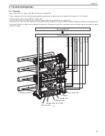
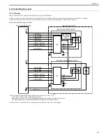
The image formation system forms a toner image on paper, which is controlled by the DC controller. It consists of four toner cartridges and the ETB unit, etc.
The DC controller controls the laser scanner unit, and forms an electrostatic latent image on the photosensitive drum based on the video signal received from the
main controller. At the same time, it controls the high-voltage power PCB, makes toner adhere to the electrostatic latent image, and then transfers it on paper.
A memory tag, which saves cartridge data, is built in the toner cartridge for each color. The DC controller detects the use condition of the toner cartridge by reading/
writing the memory tag.
F-7-1
Video data
Cartridge data
ATT
TR
DEV
PRI
PREEXP
Main
controller
PCB
DC controller PCB
High-voltage power PCB
Video signals
BL
To developing
blade
To developing
cylinder
To primary
charging roller
Pre-exposure LED
Toner cartridge
ETB unit
Laser scanner unit
Laser beam
Attraction roller
Memory tag
Содержание imageCLASS MF8450c
Страница 16: ...Chapter 1 Introduction ...
Страница 55: ...Chapter 2 Basic Operation ...
Страница 61: ...Chapter 3 Main Controller ...
Страница 75: ...Chapter 4 Original Exposure System ...
Страница 88: ...Chapter 5 Original Feeding System ...
Страница 105: ...Chapter 6 Laser Exposure ...
Страница 113: ...Chapter 7 Image Formation ...
Страница 150: ...Chapter 8 Pickup and Feed System ...
Страница 184: ...Chapter 9 Fixing System ...
Страница 200: ...Chapter 10 External and Controls ...
Страница 230: ...Chapter 11 Maintenance and Inspection ...
Страница 233: ...Chapter 12 Measurement and Adjustments ...
Страница 237: ...Chapter 13 Correcting Faulty Images ...
Страница 251: ...Chapter 13 13 13 13 3 5 PCBs 13 3 5 1 PCBs 0019 5065 imageCLASS MF9170c imageCLASS MF9150c imageCLASS MF8450c ...
Страница 256: ...Chapter 13 13 18 F 13 19 21 22 28 29 30 31 24 14 15 16 23 26 25 32 27 20 19 18 17 2 13 6 10 33 1 8 4 3 12 11 5 7 9 ...
Страница 260: ...Chapter 14 Error Code ...
Страница 272: ...Chapter 15 Special Management Mode ...
Страница 280: ...Chapter 16 Service Mode ...
Страница 322: ...Chapter 17 Upgrading ...
Страница 327: ...Chapter 17 17 4 3 Click Next F 17 4 4 Select a USB connected device and click Next F 17 5 ...
Страница 328: ...Chapter 17 17 5 5 Click Start F 17 6 6 Click Yes F 17 7 Download will be started F 17 8 ...
Страница 330: ...Chapter 18 Service Tools ...
Страница 334: ...Appendix ...
Страница 349: ......

