Chapter 6
6-3
6.2 Controlling the Laser
6.2.1 Overview
0019-5007
imageCLASS MF9170c / imageCLASS MF9150c / imageCLASS MF8450c
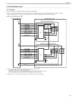
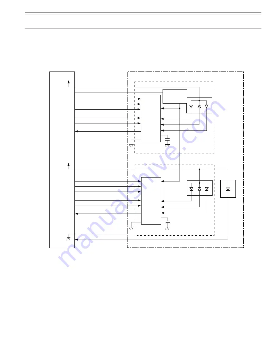
The laser control is to allow the laser driver to turn the laser diode ON/OFF according to the laser control signals sent from the DC controller.
There are two laser driver PCBs: one is for M/C and the other is for Y/Bk. The configurations of both PCBs are identical.
In the case of the laser driver for M/C
F-6-2
The DC controller sends the following signals to each laser driver IC (IC1, IC2).
- video signals (VDO, /VDO) for the image formation
- laser control signals (CTRL 0 to 2) for switching the operational mode of the laser driver circuit
- laser light intensity switch signal (LDPWRH) for switching the laser light intensity
The laser driver IC controls the laser according to the combination of the laser control signals.
+5V
DC controller PCB
Laser driver PCB
Cyan laser driver circuit
LD2CTRL0
LD2CTRL1
LD2CTRL2
VDO21,/VDO21
VDO22,/VDO22
LD2PDOUT
Magenta laser driver circuit
LD1CTRL0
LD1CTRL1
LD1CTRL2
VDO11,/VDO11
VDO12,/VDO12
LD1PDOUT
+5V
LDPWRH
IC2
LD2
BD circuit
LD1
LD2
PD
IC1
LD1
LD1
LD2
PD
C8
C14
/BD1I
Light intensity
switching
circuit
Содержание imageCLASS MF8450c
Страница 16: ...Chapter 1 Introduction ...
Страница 55: ...Chapter 2 Basic Operation ...
Страница 61: ...Chapter 3 Main Controller ...
Страница 75: ...Chapter 4 Original Exposure System ...
Страница 88: ...Chapter 5 Original Feeding System ...
Страница 105: ...Chapter 6 Laser Exposure ...
Страница 113: ...Chapter 7 Image Formation ...
Страница 150: ...Chapter 8 Pickup and Feed System ...
Страница 184: ...Chapter 9 Fixing System ...
Страница 200: ...Chapter 10 External and Controls ...
Страница 230: ...Chapter 11 Maintenance and Inspection ...
Страница 233: ...Chapter 12 Measurement and Adjustments ...
Страница 237: ...Chapter 13 Correcting Faulty Images ...
Страница 251: ...Chapter 13 13 13 13 3 5 PCBs 13 3 5 1 PCBs 0019 5065 imageCLASS MF9170c imageCLASS MF9150c imageCLASS MF8450c ...
Страница 256: ...Chapter 13 13 18 F 13 19 21 22 28 29 30 31 24 14 15 16 23 26 25 32 27 20 19 18 17 2 13 6 10 33 1 8 4 3 12 11 5 7 9 ...
Страница 260: ...Chapter 14 Error Code ...
Страница 272: ...Chapter 15 Special Management Mode ...
Страница 280: ...Chapter 16 Service Mode ...
Страница 322: ...Chapter 17 Upgrading ...
Страница 327: ...Chapter 17 17 4 3 Click Next F 17 4 4 Select a USB connected device and click Next F 17 5 ...
Страница 328: ...Chapter 17 17 5 5 Click Start F 17 6 6 Click Yes F 17 7 Download will be started F 17 8 ...
Страница 330: ...Chapter 18 Service Tools ...
Страница 334: ...Appendix ...
Страница 349: ......


