


COPYRIGHT © 1998 CANON INC. CANON DADF-A1 REV.0 DEC. 1998 PRINTED IN JAPAN (IMPRIME AU JAPON)
2-1
CHAPTER 2 BASIC OPERATION
I. BASIC CONSTRUCTION
A. Outline of the Electrical Circuitry
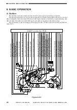
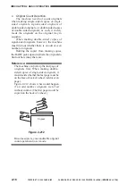
The machine’s electrical mechanisms are controlled by the DADF controller PCB. A
microprocessor (CPU) is used on the DADF controller PCB, and the microprocessor reads the input
signals from the sensors and the copier and generates signals used to drive DC loads (motors,
solenoids) at such times as programmed in advance.
Sensor
Variable
resistor
DADF controller PCB
CPU
(Q1)
ROM
(Q2)
RAM
(Q4)
Communication
IC(Q3)
24V
J2-1
J1-6
5V
5 VDC
power
supply
Power supply
circuit
Copierk
Motor
Solenoid
Clutch
Brake
Indicator
LED PCB
Motor
Figure 2-101


