background image

15

Installation/Connection

Installation/Connection

How to Carry the Main Unit

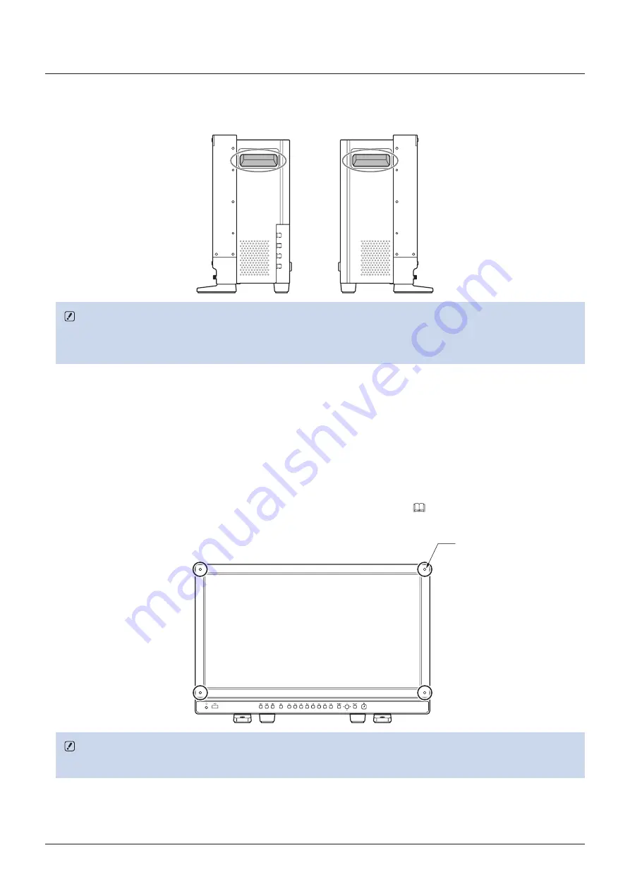
When lifting the video display, please use the carrying handles on the display’s sides.

CAUTION

•  When unpacking, carrying, installing, or connecting the main unit, please note that at least two people are required.
•  When carrying the video display, handle it carefully not to touch or damage the screen.

Procedures to attach the protection panel

You can attach the protection panel to protect the screen when carrying the video display or when using it outdoors.

1.  Unscrew the four screws on the front face.

Use a 1.5 mm hexagonal key.
Do not lose the removed screws. Do not use these screws for other purposes.

2.  Place the protection panel by aligning its corners with the screw holes. (

77).

Take care when attaching the panel in order to avoid damaging it.

4×M3 
7 mm deep (Max.)

CAUTION

•  Avoid touching the screen during this step as it may damage it.

Содержание DP-V2420

Страница 1: ...play Before use be sure to read this guide including the safety and handling precautions Reading this guide will help you learn to use the video display properly Store this guide safely so that you can use it in the future English ...

Страница 2: ... the Power of the Main Unit 21 Installing the AC power cord clamp HC 01 Included 21 Operating the Video Display 22 Operating the jog dial 22 Basic operations to use the OSD menu 22 Adjusting Image Quality While Viewing the Entire Image 24 Temporarily Saving Parameters Anchor Point Setting 25 Enlarging the display Zoom function 25 Adjusting image quality for each screen in two screen display 26 Cal...

Страница 3: ... 61 System Settings 69 Signal Information 74 System Information 74 Main specifications Performance 75 Dimensions 77 Appendix 78 Supported Signal Format 78 Image Frame Display 92 Error Messages 95 Troubleshooting 97 Software Used in This Product 99 Index 101 ...

Страница 4: ...ence information CAUTION Indicates an item you must observe Trademarks HDMI HDMI logo and High Definition Multimedia Interface are trademarks or registered trademarks of HDMI Licensing LLC in the U S and other countries VESA is a registered trademark or trademark of Video Electronics Standards Association in the U S and other countries Other product and company names herein are trademarks or regis...

Страница 5: ...One Canon Park Melville NY 11747 U S A Tel No 631 330 5000 For the customers in Canada CAN ICES 3 A NMB 3 A For the customers in Europe Warning This is a class A product In a domestic environment this product may cause radio interference in which case the user may be required to take adequate measures CANON INC 30 2 Shimomaruko 3 chome Ohta ku Tokyo 146 8501 Japan CANON EUROPA N V Bovenkerkerweg 5...

Страница 6: ... places Doing so can cause fire electric shock or malfunction Next to a window when it is raining or snowing Places subject to high humidity and dusty places Places exposed to water drops or moisture such as bathrooms or watering places Places directly exposed to soot smoke or steam or nearby heaters and humidifiers Places where flammable gases may be present Places exposed to direct sunlight Do n...

Страница 7: ...rcumstances such as the presence of smoke or strange sounds or smell turn off immediately the video display and unplug the power plug from the power outlet Continued use can cause fire or electric shock Do not obstruct the access to the power plug so it can always be easily unplugged Failing to disconnect the power plug immediately after unusual circumstances have occurred can cause fire or electr...

Страница 8: ...ng or falling 17 Taking such measures can be effective in reducing the risk of injury or damage but the effectiveness of the prevention measures cannot be guaranteed in all earthquakes Always follow the specified procedure to install the video display 15 If the installation is not performed correctly the video display may tilt or fall and cause injury Inspect the condition of the installation abou...

Страница 9: ...tness may degrade and color may change due to aging About Temporary Screen burn in If a stationary image is displayed for a prolonged period screen burn in may occur where you see remnants of what was displayed This is a characteristic of LCD and is not a failure However this is only temporary and will disappear when playing video About the LCD screen The screen is produced using extremely high pr...

Страница 10: ...age the LCD panel The screen may be scratched if wiped too hard with a cleaning cloth with foreign particles attached When the screen is extremely dirty wipe with soft cloth such as cleaning cloth or eye glasses cleaning cloth moistened with water diluted neutral detergent Use a blower to remove dust from the surface of the screen Wipe dirt on cabinet with a soft cloth If the screen is very dirty ...

Страница 11: ...ngent Wave Ltd external sensor or USB memory can be connected to the USB port Separately sold Display Controller CL 01 can be connected to the LAN terminal Supports Square Division and 2 Sample Interleave video signal transport methods Includes a multi display function 4 or 2 screens HDR and SDR content can be displayed for comparison Equipped with a HDMI input terminal Link with digital cinema ca...

Страница 12: ...s up one level in a menu 22 Jog dial Moves the selection frame within the OSD menu changes the settings up down left right rotation and determines press the selection 22 RESET button Resets the items to be adjusted using the slider and entered characters 22 9 Power button Turns power On Off 21 A q Power indicator Displays the status of the main unit The brightness of the power indicator can be set...

Страница 13: ... A d 3G HD SDI output terminal Pass through output corresponding to 3G HD SDI input terminal A f 3G HD SDI input terminal Used to input SDI signals 19 A g Cord clamp mounting hole For installing the AC power cord clamp Included 21 A h AC power input terminal Connection for the provided AC power supply cord 21 Side face of the main unit A j Right side Left side A j Carrying handle Used to install c...

Страница 14: ... that may have excessive voltage to the terminal of the video display when connecting peripheral devices Pass through SD SDI signals are not output correctly Note Both FAT16 and FAT32 USB memory devices are supported Proper operation cannot be guaranteed for all USB memories It may take 10 seconds or more for the USB memory to be recognized If the function to save data on a USB memory is executed ...

Страница 15: ... damage the screen Procedures to attach the protection panel You can attach the protection panel to protect the screen when carrying the video display or when using it outdoors 1 Unscrew the four screws on the front face Use a 1 5 mm hexagonal key Do not lose the removed screws Do not use these screws for other purposes 2 Place the protection panel by aligning its corners with the screw holes 77 T...

Страница 16: ...h from the left and right stands Do not lose the removed screws Do not use these screws for other purposes Attaching 1 Place the display with the screen facing down on a soft cloth or cushioning material that is larger than the display 2 Align the position of the stand and screw hole on the video display Alight the convex part of the stand and concave part of the video display 3 Front stand Fix th...

Страница 17: ...se screws that fit the screw holes The screw hole size is shown below Screw hole 2 4 5 CAUTION When securing the main unit to a table or desk please ensure a table or desk is strong enough to carry the weight of the main unit It is recommended to obtain assistance from another person when performing this step Avoid touching the screen during this step as it may damage it ...

Страница 18: ... temperature may increase causing a failure or overheating In order to maintain the operating temperature condition of the video display 0 C to 40 C make a space of at least 1U 4 4 cm above and below and at least 4 cm 1 6 in space from its back Make a sufficient space from peripheral equipment secure vents or install a ventilation fan When installing the video display on a wall make sufficient spa...

Страница 19: ...inal Quad Link Square Division 3G SDI Top left Mapping signal Input A Single input system Top right Mapping signal Input B Bottom left Mapping signal Input C Bottom right Mapping signal Input D Quad Link 2 Sample Interleave Link 1 Input A Link 2 Input B Link 3 Input C Link 4 Input D Quad Link HD SDI Link 1 Input A Single input system Link 2 Input B Link 3 Input C Link 4 Input D Dual Link 2 Sample ...

Страница 20: ...ough output Even during full screen display when a signal is input from SDI terminal A s IN terminal you can connect the cable to SDI terminal A s OUT terminal HDMI input signal HDMI input terminal CAUTION Use a HDMI cable with the High Speed logo that complies with the HDMI standard When a non compliant HDMI standard cable is used the video display may not work normally for example a video become...

Страница 21: ...after turning on the power before using Installing the AC power cord clamp HC 01 Included Install the AC power cord clamp before connecting the AC power cord to the main unit 1 Insert the AC power cord clamp connector into the cord clamp mounting hole 1 2 Connect the AC power cord to the main unit 2 3 Secure the AC power cord in place with the holder 3 4 Press the holder against the main unit 4 Ma...

Страница 22: ...are described below MENU button Opens closes the OSD menu or moves up one level in a menu RESET button Resets the items to be adjusted using the slider and entered characters Jog dial Up down left right rotation Used to move to a different item and change settings Press Confirms settings or moves the selection frame up down 1 level Basic operations to use the OSD menu This section describes basic ...

Страница 23: ...he main menu on the top screen and then press the MENU button to exit the menu Note Press the RESET button to return Contrast Brightness Chroma Sharpness Power Saturation Offset and Slope to the factory default during adjustment In User 1 7 mode where you are performing calibration the setting returns to the value after calibration instead of the factory default To adjust image quality warming up ...

Страница 24: ...djusting Gain R G B Bias R G B under Color Temperature You can adjust RGB all at once or individually when the slider for adjusting Gain R G B and Bias R G B are displayed 1 Switch the guide in the upper right area of the slider screen using the jog dial The indication changes to RGB R G and B 2 When adjustments are completed press the jog dial The screen returns to the original OSD menu Adjusting...

Страница 25: ...ote Executing Reset under Adjustment or Reset All Settings under System Settings resets saved anchor points and the settings return to their factory default values When calibration is performed in User 1 7 under Picture Mode the values are saved as anchor points Enlarging the display Zoom function 53 The zoom display position can be adjusted and the zoom magnification 2x 4x 8x can be selected 1 Pr...

Страница 26: ...ect Picture Mode in the screen on the right Picture Mode R 4 Adjusting the image quality 5 When adjustments are completed press the jog dial The screen returns to the original OSD menu Switching the target screen When the OSD menu is open In the Adjustment main menu press the jog dial s button In the Adjustment main or sub menu press the CH1 button When the OSD menu is not being displayed Move the...

Страница 27: ...layed press the jog dial and select OK If the message Calibration error is displayed Calibration has been terminated due to an error The main unit returns to the state before calibration 95 To cancel calibration Press the jog dial during calibration and select Cancel The main unit returns to the state before calibration Note Due to the characteristic of LCD panel and individual difference of CA 31...

Страница 28: ...Canon website 5 Select Select LUT using the jog dial Selects User LUT 1 8 Gamma LUT 1 8 Gamut LUT 1 8 6 Select the standard color gamut using the jog dial Select the color gamut used when creating the LUT when Gamut LUT under LUT Type is selected 7 Select Execute using the jog dial When the confirmation screen appears select OK Import starts Note The LUT file is proprietary to Canon Video Display ...

Страница 29: ...change the name of the file to be exported to the USB memory within 16 one byte characters including alphabetical characters numbers and symbols Select Execute When the confirmation screen appears select OK Export starts Importing Select Target from USB or User 1 3 Specify the destination to save the file to be imported Select Filename In Settings select All or Main Menu name Select Execute When t...

Страница 30: ...000 CDL import files are recognized Set Date Time 69 This section describes how to set the Date Time The Date Time of this video display will be reset if the power cord is not connected for about 20 days 1 Press the MENU button to open the OSD menu 2 Select System Settings Date Time A screen to input the Date Time appears 3 Set the Date Time using the jog dial The selection frame moves and numbers...

Страница 31: ...cel or pressing MENU button before selecting OK the settings will be reset and the previous screen will be displayed To erase the character in the selection frame press the RESET button of the video display Using the Function F Buttons You can assign functions to the F buttons on the video display to execute them instantly 1 Press the MENU button to open the OSD menu 2 Select System Settings Funct...

Страница 32: ...onfiguration 3G HD SDI HDMI 3G SDI RAW Select Input Signal Automatic Automatic Automatic Image Division Automatic Automatic Automatic Format Automatic Automatic Automatic Internal Sync Off Off Off Channel Name Blank Blank Blank Picture Mode ITU R BT 709 ITU R BT 709 Canon Log Picture Mode R ITU R BT 709 ITU R BT 709 Canon Log Audio Input Input A Input A Input A Marker TC WFM VEC Input Input A Inpu...

Страница 33: ...tput Transform Output Transform Surround Color Range CDL User LUT Type CDL Preset User LUT Power Saturation Offset Slope CDL User LUT Bypass Detail Settings CDL Export CDL Import CDL Preset Name Anchor CDL Reset CDL Detail Settings Peak Luminance Control LUT Import LUT Name LUT Delete YCbCr Color Matrix 2020 Constant Luminance 2020 Gamut Mapping Hybrid Log Gamma System HDR SDR View ...

Страница 34: ...Division Format Internal Sync Channel Name Picture Mode Picture Mode R Audio Input Marker TC WFM VEC Input Picture Function Target Separator Display Settings 52 Screen Scaling Scaling Method Zoom Zoom Preset Magnification Position Frame Hold Background Color I PsF PsF I P Conversion Film Cadence Audio Settings 55 SDI Group CH L R SDI CH L R HDMI Volume Audio Switch ...

Страница 35: ...tion V Position Safety Zone Marker 1 2 Enable Aspect Ratio Area Size Rate Width dot Height dot Shape Line Width Line Color Line Brightness H Position V Position Area Marker Enable H Position V Position Width dot Height dot Mask Line Line Width Line Color Line Brightness Center Marker Enable Size Line Width Line Color Line Brightness ...

Страница 36: ...ency Range Color False Color Time Code Enable Type Size Position Wave Form Monitor Enable Select Signal Display Type Select Line Position Scale Guide Standard Level High Standard Level Low Color Vector Scope Enable Target Position Audio Level Meter Enable Channel Number SDI Channel Number HDMI Peak Hold Standard Level Test Pattern ...

Страница 37: ...Gamut Gamma Color Temperature Color Range Display Color Gamut Automatic Adjustment ARRI User LUT Color Gamut Color Range Area Marker Fan Camera Information System Settings 69 Function Channel Button Display Function Display Function CDL Display Channel Language Date Time Network Display Name Power Indicator Brightness Display Button LED Fan Settings Fan Control Fan Stop Compatible Settings Protect...

Страница 38: ...38 OSD Menu Export Import Export Import Power on Setting Reset All Settings Signal Information 74 System Information 74 ...

Страница 39: ... Peak Luminance Control is On Contrast Peak Control is displayed 0 to 12000 Note In Multi View Dual display when right screen is selected as the target screen it is not possible to adjust the Contrast after selecting Picture Mode The Contrast value is same on both screens Brightness Adjusts the black level of the image Increments of 1 500 to 500 Chroma Adjusts the color saturation of the image col...

Страница 40: ...DCI P3 to DCI DCI P3 to 709 ITU R BT 2020 to 709 Modes where the color gamut is converted to monitor Cinema Gamut DCI P3 BT 2020 and DCI P3 videos recorded by the CINEMA EOS C500 C500PL and C300 Mark II ACESproxy Displays the color gamut of ACESproxy when Canon Log is selected Gamut LUT 1 to Gamut LUT 8 Selects an external LUT Note For checking the video captured with Cinema EOS cameras please ref...

Страница 41: ...GB Off 1 0 2 2 2 35 2 4 2 6 ITU R BT 1886 Gamma LUT 1 to Gamma LUT 8 DCI P3 Off 1 0 2 2 2 35 2 4 2 6 ITU R BT 1886 Canon Log Canon Log HDR Canon Log 2 Canon Log 2 HDR Canon Log 3 Canon Log 3 HDR SMPTE ST 2084 Gamma LUT 1 to Gamma LUT 8 Canon Log User 1 7 SMPTE C Off 1 0 2 2 2 35 2 4 2 6 ITU R BT 1886 Canon Log Canon Log HDR SMPTE ST 2084 Gamma LUT 1 to Gamma LUT 8 EBU Off 1 0 2 2 2 35 2 4 2 6 ITU ...

Страница 42: ...id Log Gamma Y 100 to 1000 2000 4000 Hybrid Log Gamma RGB 100 to 1000 2000 Setting procedures The procedures below use Canon Log 2 HDR as an example When the maximum value 1600 is specified the 1600 dynamic range of Canon Log 2 is assigned to the dynamic range of the video display Although the brightness in appearance lowers you can check the dynamic range included in video signals When 1200 is sp...

Страница 43: ...rround process specified by ACESproxy Color Range Sets the quantization range Automatic Sets the range based on signal information automatically Full 0 255 Sets to Black level 0 White level 1023 10 bit 4095 12 bit Limited 1 16 235 Limits the black and white range Black level 64 10 bit 256 12 bit White level 940 10 bit 3760 12 bit Limited 2 16 255 Limits the black range Black level 64 10 bit 256 12...

Страница 44: ...et CDL 1 to CDL 15 All File Type CCC CDL Execute CDL Import Imports CDL parameters Filename CDL Preset CDL 1 to CDL 15 Execute CDL Preset Name You can specify the name of preset mode within 16 one byte characters including alphabetical characters numbers and symbols Anchor CDL You can temporarily save parameters for Power Saturation Offset and Slope and recover the values anchor point setting Rese...

Страница 45: ...LUT LUT Type User LUT Gamma LUT Gamut LUT Select the LUT type Select LUT Selects User LUT 1 8 Gamma LUT 1 8 Gamut LUT 1 8 Delete Deletes LUT YCbCr Color Matrix Sets the matrix conversion method for input signals in YCbCr format Automatic Matrix coefficient is set in conformance with the ITU R BT 2020 standard when the Picture Mode or Color Gamut setting is ITU R BT 2020 and in conformance with the...

Страница 46: ...s set to high brightness it may be calibrated beyond the brightness adjustment range and set lower than the target value depending on the Color Temperature setting In that case set the Luminance again Cannot be run in the picture mode of the right screen in the Multi View Dual display Copy Picture Mode When User 1 7 is selected for Picture Mode the content of the selected picture mode is copied Th...

Страница 47: ...20 Adobe RGB Color Range Automatic Automatic Automatic Automatic Automatic Input Transform Output Transform Output Transform Surround CDL Preset CDL 1 CDL 2 CDL 3 CDL 4 CDL 5 User LUT User LUT 1 User LUT 1 User LUT 1 User LUT 1 User LUT 1 Peak Luminance Control Off Off Off Off Off YCbCr Color Matrix Automatic Automatic Automatic Automatic Automatic 2020 Constant Luminance Non constant Luminance No...

Страница 48: ...omatic Automatic Input Transform Automatic Automatic Output Transform DCI P3 DCI P3 Output Transform Surround Dark Surround Dark Surround CDL Preset CDL 6 CDL 7 13 CDL 14 CDL 15 User LUT User LUT 1 User LUT 1 User LUT 1 User LUT 1 Peak Luminance Control Off Off Off Off YCbCr Color Matrix Automatic Automatic Automatic Automatic 2020 Constant Luminance Non constant Luminance Non constant Luminance N...

Страница 49: ...ording to the input signal SD SDI Only Single Input A to Single Input D can be selected HDMI This is fixed to Automatic Dual Input can be set in the case of 3G HD SDI or 3G SDI RAW Image Division Sets the display method when Input Configuration is set to 3G HD SDI and Select Input Signal is set to Quad Input or Dual Input Two division methods Square Division and 2 Sample Interleave are supported f...

Страница 50: ...s when Square Division is selected On Force synchronization Off Do not force synchronization Channel Name Sets the name of the selected channel You can input up to 16 alphanumeric characters Picture Mode Sets the Picture Mode Picture Mode R Sets the picture mode for the right screen in the Multi View Dual display Audio Input Sets the audio terminal Terminals that can be selected differ according t...

Страница 51: ...y default settings for each channel is shown in the following table CH CH1 CH2 CH3 CH4 to CH30 Input Configuration 3G HD SDI HDMI 3G SDI RAW Select Input Signal Automatic Automatic Automatic Automatic Image Division Automatic Automatic Automatic Automatic Format Automatic Automatic Automatic Automatic Internal Sync Off Off Off Off Channel Name Blank Blank Blank Blank Picture Mode ITU R BT 709 ITU ...

Страница 52: ...isplayed on the screen Native Input Resolution Displays the input signal without scaling 1920x1080 original 200 Doubles the vertical and horizontal dimensions 1920x1080 3840x2160 Automatic Enlarges to full screen 1920x1080 3840x2160 Note In the following cases the maximum magnification is 200 even if Automatic is selected When Peaking or False Color is On When Multi View Dual is selected ...

Страница 53: ...ion is 4096x2160 3840x2160 2048x1080 or 1920x1080 Zoom Preset Sets the zoom display method There are three presets Zoom 1 Zoom 2 Zoom 3 Off Magnification Sets the display scale of zoom x2 x4 x8 Position The zoom adjustment screen is displayed Use the jog dial to adjust the display position Note The zoom function cannot be used in the following cases During execution of Playback File under Screen C...

Страница 54: ...giving preference to image quality by detecting paired fields Interlace Interpolates using two adjacent fields giving priority to speed I P Conversion Sets the interlaced signal I P conversion method Image Priority This mode gives priority to image quality Processing time will be longer than Speed Priority Speed Priority This mode gives priority to speed Film Cadence Sets the film cadence mode 2 2...

Страница 55: ... SDI Sets the audio to be output from the two channels L R of the headphone respectively The options differ according to the SDI Group setting When CH1 CH8 is selected for SDI Group CH1 CH8 When CH9 CH16 is selected for SDI Group CH9 CH16 CH L R HDMI Sets the audio to be output from the two channels L R of the headphone respectively CH1 CH8 Volume Sets the volume Increments of 1 0 to 100 30 Audio ...

Страница 56: ...n of Playback File under Screen Capture When a Test Pattern is displayed Enable Switches the aspect marker On Off On Off Mask Switches the mask color Mask is the blanking area outside the range of the marker Black Half 50 gray Off Turns mask off Aspect Ratio Sets the aspect ratio of the aspect marker 16 9 15 9 14 9 13 9 4 3 2 39 1 2 35 1 1 896 1 1 85 1 1 66 1 Variable The aspect ratio can be enter...

Страница 57: ...atio Sets the aspect ratio of the safety zone marker 16 9 15 9 14 9 13 9 4 3 2 39 1 2 35 1 1 896 1 1 85 1 1 66 1 Variable The aspect ratio can be entered as a numeric value when you select Variable 0 01 1 increments The grayed out slider becomes active and can be used to set the aspect ratio 1 00 1 to 3 00 1 1 78 1 Note When Area Size is set to Variable dot you cannot select Aspect Ratio Area Size...

Страница 58: ...one marker line Thick Normal Thin Line Color Sets the color of the safety zone marker line White Red Green Blue Yellow Cyan Magenta Line Brightness Sets the brightness of the safety zone marker line High Low H Position Adjusts the marker horizontal position with the set aspect and size 65 to 65 0 V Position Adjusts the marker vertical position with the set aspect and size 35 to 35 0 ...

Страница 59: ...Sets the start position x coordinate to draw the rectangle in increments of 2 0 to 4086 240 V Position Sets the start position y coordinate to draw the rectangle in increments of 2 0 to 2150 120 Width dot Sets the width of the rectangle in increments of 2 10 to 4096 240 Height dot Sets the height of the rectangle in increments of 2 10 to 2160 120 Mask Switches the mask color in the marker Black Ha...

Страница 60: ...White Red Green Blue Yellow Cyan Magenta Line Brightness Sets the brightness of the center marker line High Low Grid Marker Grid Marker is marker used to check the horizontal and vertical position Note Grid Marker is not displayed when an enlarged image is displayed Enable Switches the grid marker On Off On Off Distance Sets the horizontal and vertical line distance 160 dots 240 dots 320 dots Line...

Страница 61: ...video in monochrome On Off Frequency Sets the central frequency of contour enhancement signals Peaking 1 Low Middle High Peaking 2 Low Middle High Range Sets the width of the range to be colored 3 3 0 Color Sets the color to be used White Red Green Blue Yellow Cyan Magenta False Color When set to On different colors are displayed according to video s brightness level so that you can check the expo...

Страница 62: ...eft Top Right Bottom Left Bottom Right Note This setting becomes invalid in the Multi View Dual display Wave Form Monitor Configures various settings for the wave form monitor On the wave form monitor the horizontal axis shows the horizontal resolution of the video and the vertical line shows the signal level 255 4 0 50 100 0 Signal level IRE Horizontal resolution of video Note Wave form monitor c...

Страница 63: ...t the scale Guide A guide is displayed at the specified position Guide is not displayed when 255 is selected 1 to 255 Standard Level High Sets the standard display level high Standard Level High is not displayed when 255 is selected 190 to 255 Standard Level Low Sets the standard display level low Standard Level Low is not displayed when 0 is selected 0 to 64 Color Sets the signals to be displayed...

Страница 64: ...es When an enlarged image is displayed When Frame Hold during interlace signal or PsF signal or False Color is On When Peaking 1 or Peaking 2 is selected During execution of Playback File under Screen Capture While Test Pattern is displayed Only the signal set by Marker TC WFM VEC Input is displayed in the Multi View Quad or Multi View Dual display When Vector Scope is set to On Wave Form Monitor ...

Страница 65: ...SDI Group 2CH CH9 CH10 4CH CH9 CH12 6CH CH9 CH14 8CH CH9 CH16 Channel Number HDMI Sets the number of channels displayed when HDMI signal is input 2CH CH1 CH2 4CH CH1 CH4 6CH CH1 CH6 8CH CH1 CH8 Peak Hold When set to On one second of audio signal at the peak is kept On Off Standard Level Sets the standard level 40 to 0 20 Test Pattern Sets the test pattern built into the main unit White Gray 20 Bla...

Страница 66: ...2420 or PC color may not be played back precisely Finish Playback File Finishes playback Various Function Displays the function list to execute functions Monochrome On Off Blue Only On Off Red Off On Off Green Off On Off Blue Off On Off Banner On Off 1 Function Guide On Off 2 OSD Position Mode 1 Mode 2 3 OSD Size Large Small 4 1 Banner When Banner is set to Off the banner is displayed only when yo...

Страница 67: ...I P3 DCI P3 Color Gamut Gamma The image quality of the display corresponds to the gamma and color gamut of the camera On Off Color Temperature The image quality of the display corresponds to the color temperature of the camera On Off Color Range The image quality of the display corresponds to the range of the camera On Off Display Color Gamut Sets the color gamut shown on the display when the came...

Страница 68: ...fan is stopped to lower the internal temperature On Off Note This can be operated in On with REC signals supported by this function Cinema EOS cameras Canon professional use video cameras ARRI cinema cameras If the temperature inside the main unit increases while the fan is off the message Fan will be rotated as the temperature is high is displayed and the fan starts rotating approximately ten sec...

Страница 69: ...wer F5 CDL Offset F6 CDL Slope F7 CDL Saturation F8 CDL User LUT Bypass Note When changing channels with Channel UP DOWN the channels with Input Configuration 49 set to are skipped When the Backlight Control setting is switched using an F button the information is applied to Backlight Control in Picture Mode Likewise when any marker settings are changed those changes will be applied to Enable unde...

Страница 70: ...rates at a faster speed than usual before and after the fan is stopped to lower the internal temperature On Off Note If the message Invalid operation due to high temperature is displayed the fan cannot be stopped even when On is selected for this item Wait until the internal temperature lowers If the temperature inside the main unit increases while the fan is off the message Fan will be rotated as...

Страница 71: ...or imported to User 1 to 3 under Target Data exported from this product may not be imported to products of which firmware version is earlier than the version of this product To import data update the firmware to the latest version Export Target Select the export destination USB Export to a USB memory User 1 3 Export to the built in memory of the main unit Filename Factory default is dinfo_dpv2420 ...

Страница 72: ... Hybrid Log Gamma RGB Picture Mode SMPTE C Gamma LUT 1 to Gamma LUT 8 EBU CDL CDL Preset ITU R BT 709 User LUT ITU R BT 2020 CDL R Adobe RGB CDL G DCI P3 CDL B User 1 to User 7 CDL Slope Canon Log CDL Offset ACESproxy CDL Power Color Gamut SMPTE C CDL Saturation EBU CDL SOP Sat ITU R BT 709 CDL User LUT Bypass ITU R BT 2020 CDL Export Import Adobe RGB Channel Settings Channel UP DCI P3 Channel DOW...

Страница 73: ...VEC Background Color Wave Form Monitor Audio Settings SDI Group WFM Select Signal CH L Vector Scope CH R Audio Level Meter Volume Monochrome Audio Switch Blue Only Marker Settings Marker Preset Red Off Marker 1 Green Off Marker 2 Blue Off Marker 3 Camera Information Marker 4 System Settings Hide OSD Marker 5 Fan Stop Aspect Marker Safety Zoon Marker 1 Safety Zoon Marker 2 Area Marker Center Marker...

Страница 74: ...I 4 4 4 4 GBRA 10 bit 24 00 Progressive Progressive Transport Picture Single Link_1 Channel Input Configuration Format Resolution Picture Rate I P PsF Pixel Encoding Color Depth Matrix Range EOTF Max Luminance Peak Avg Display Luminance Max Min White Point Primary Color Red Primary Color Green Primary Color Blue CH4 HDMI Automatic 4096x2160 60 00P 4 2 2 YCbCr 10 bit ITU R BT 709 Full SMPTE ST 2084...

Страница 75: ... V AC Rated Frequency 50 60 Hz Power consumption At maximum load including change in brightness through aging Approximately 510 W At factory shipment Approximately 180 W Environmental Conditions Operating Temperature and humidity 0 40 C 32 104 F 20 85 RH no condensation recommended 15 30 C 59 86 F Pressure 700 1060 hPa Storage Transporting Temperature and humidity 20 40 C 4 104 F 20 85 RH no conde...

Страница 76: ...thru systems Head phone 1 stereo mini jack Supported impedance 32 Ω to 64 Ω Control USB 1 USB A receptacle terminal Universal Serial Bus Specification Revision 2 0 compliant LS Low Speed FS Full Speed HS High Speed mode compatible Compliant with Enhanced Host Controller Interface Specification for Universal Serial Bus Revision 1 0 LAN 1 RJ 45 terminal Compliant with IEEE802 3 10BASE TX IEEE802 3u ...

Страница 77: ... 493 19 4 355 4 14 0 594 23 4 378 14 9 312 12 3 399 15 7 567 6 22 3 Center of panel 6 M4 Depth 5 0 2 Max 100 3 9 100 3 9 100 3 9 230 9 1 2 4 5 0 2 235 9 3 195 7 7 47 5 1 9 61 2 4 40 1 6 4 M4 Depth 8 0 3 Max 160 6 3 15 0 6 Unit mm inch Front Rear Side Bottom ...

Страница 78: ... 00 Hz 1920x1080P 25 00 Hz 1920x1080PsF 25 00 Hz 1920x1080P 23 98 24 00 Hz 1920x1080PsF 23 98 24 00 Hz 2048x1080i 59 94 60 00 Hz 2048x1080i 50 00 Hz 2048x1080P 29 97 30 00 Hz SMPTE 292 1 SMPTE 428 9 SMPTE 428 19 SMPTE 2048 2 2048x1080PsF 29 97 30 00 Hz 2048x1080P 25 00 Hz 2048x1080PsF 25 00 Hz 2048x1080P 23 98 24 00 Hz 2048x1080PsF 23 98 24 00 Hz 3G SDI Level A 1280x720P 59 94 60 00 Hz 4 4 4 RGB 4...

Страница 79: ...1 SMPTE 274M 4 2 2 YCbCr 12 bit 1920x1080P 25 00 Hz 4 4 4 RGB 4 4 4 YCbCr 12 bit 10 bit 4 2 2 YCbCr 12 bit 1920x1080PsF 25 00 Hz 4 4 4 RGB 10 bit 12 bit 4 4 4 YCbCr 12 bit 4 4 4 YCbCr 10 bit SMPTE 425 1 SMPTE 274M 4 2 2 YCbCr 12 bit 1920x1080P 23 98 24 00 Hz 4 4 4 RGB 4 4 4 YCbCr 12 bit 10 bit 4 2 2 YCbCr 12 bit 1920x1080PsF 23 98 24 00 Hz 4 4 4 RGB 10 bit 12 bit 4 4 4 YCbCr 12 bit 4 4 4 YCbCr 10 ...

Страница 80: ...SMPTE 425 1 SMPTE 2048 2 4 2 2 YCbCr 12 bit 2048x1080P 25 00 Hz 4 4 4 RGB 12 bit 10 bit SMPTE 425 1 SMPTE 428 9 SMPTE 428 19 SMPTE 2048 2 4 4 4 X Y Z 12 bit 4 4 4 YCbCr 12 bit 10 bit SMPTE 425 1 SMPTE 2048 2 4 2 2 YCbCr 12 bit 2048x1080PsF 25 00 Hz 4 4 4 RGB 12 bit 10 bit SMPTE 425 1 SMPTE 428 9 SMPTE 428 19 SMPTE 2048 2 4 4 4 X Y Z 12 bit 4 4 4 YCbCr 12 bit 10 bit SMPTE 425 1 SMPTE 2048 2 4 2 2 Y...

Страница 81: ...bit 10 bit 4 2 2 YCbCr 12 bit 1920x1080P 25 00 Hz 4 4 4 RGB 4 4 4 YCbCr 12 bit 10 bit 4 2 2 YCbCr 12 bit 1920x1080PsF 25 00 Hz 4 4 4 RGB 4 4 4 YCbCr 12 bit 10 bit 4 2 2 YCbCr 12 bit 1920x1080P 23 98 24 00 Hz 4 4 4 RGB 4 4 4 YCbCr 12 bit 10 bit 4 2 2 YCbCr 12 bit 1920x1080PsF 23 98 24 00 Hz 4 4 4 RGB 4 4 4 YCbCr 12 bit 10 bit 4 2 2 YCbCr 12 bit 2048x1080P 59 94 60 00 Hz 4 2 2 YCbCr 10 bit SMPTE 425...

Страница 82: ...Y Z 12 bit 4 4 4 YCbCr 12 bit 10 bit SMPTE 425 1 SMPTE 372 SMPTE 2048 2 4 2 2 YCbCr 12 bit 2048x1080P 25 00 Hz 4 4 4 RGB 12 bit 10 bit SMPTE 425 1 SMPTE 372 SMPTE 428 9 SMPTE 428 19 SMPTE 2048 2 4 4 4 X Y Z 12 bit 4 4 4 YCbCr 12 bit 10 bit SMPTE 425 1 SMPTE 372 SMPTE 2048 2 4 2 2 YCbCr 12 bit 2048x1080PsF 25 00 Hz 4 4 4 RGB 12 bit 10 bit SMPTE 425 1 SMPTE 372 SMPTE 428 9 SMPTE 428 19 SMPTE 2048 2 ...

Страница 83: ...3 SMPTE 428 9 SMPTE 428 19 SMPTE 2048 2 4 4 4 X Y Z 4 2 2 YCbCr 12 bit 2048x1080P 50 Hz 4 4 4 RGB 4 4 4 YCbCr 12 bit 10 bit 4 4 4 X Y Z 4 2 2 YCbCr 12 bit 2048x1080P 47 95 48 Hz 4 4 4 RGB 4 4 4 YCbCr 12 bit 10 bit 4 4 4 X Y Z 4 2 2 YCbCr 12 bit Dual Link 3G SDI Level B 1920x1080P 59 94 60 Hz 4 4 4 RGB 4 4 4 YCbCr 12 bit 10 bit SMPTE 425 3 SMPTE 372 SMPTE 274M 4 2 2 YCbCr 12 bit 1920x1080P 50 Hz 4 ...

Страница 84: ... B 3840x2160P 29 97 30 Hz 4 2 2 YCbCr 10 bit SMPTE 425 3 SMPTE 372 SMPTE 274M 3840x2160P 25 Hz 3840x2160P 23 98 24 Hz 4096x2160P 29 97 30 Hz SMPTE 425 3 SMPTE 372 SMPTE 2048 2 4096x2160P 25 Hz 4096x2160P 23 98 24 Hz Quad Link HD SDI 3840x2160i 59 94 60 00 Hz 4 2 2 YCbCr 10 bit SMPTE 292 1 SMPTE 274M 3840x2160i 50 00 Hz 3840x2160P 29 97 30 00 Hz 3840x2160PsF 29 97 30 00 Hz 3840x2160P 25 00 Hz 3840x...

Страница 85: ...bit 12 bit 4 4 4 YCbCr 12 bit 4 4 4 YCbCr 10 bit SMPTE 425 1 SMPTE 274M 4 2 2 YCbCr 12 bit 3840x2160P 25 00 Hz 4 4 4 RGB 4 4 4 YCbCr 12 bit 10 bit 4 2 2 YCbCr 12 bit 3840x2160PsF 25 00 Hz 4 4 4 RGB 10 bit 12 bit 4 4 4 YCbCr 12 bit 4 4 4 YCbCr 10 bit SMPTE 425 1 SMPTE 274M 4 2 2 YCbCr 12 bit 3840x2160P 23 98 24 00 Hz 4 4 4 RGB 4 4 4 YCbCr 12 bit 10 bit 4 2 2 YCbCr 12 bit 3840x2160PsF 23 98 24 00 Hz...

Страница 86: ...Y Z 12 bit 4 4 4 YCbCr 12 bit 10 bit SMPTE 425 1 SMPTE 2048 2 4 2 2 YCbCr 12 bit 4096x2160P 25 00 Hz 4 4 4 RGB 12 bit 10 bit SMPTE 425 1 SMPTE 428 9 SMPTE 428 19 SMPTE 2048 2 4 4 4 X Y Z 12 bit 4 4 4 YCbCr 12 bit 10 bit SMPTE 425 1 SMPTE 2048 2 4 2 2 YCbCr 12 bit 4096x2160PsF 25 00 Hz 4 4 4 RGB 12 bit 10 bit SMPTE 425 1 SMPTE 428 9 SMPTE 428 19 SMPTE 2048 2 4 4 4 X Y Z 12 bit 4 4 4 YCbCr 12 bit 10...

Страница 87: ...bCr 10 bit SMPTE 425 5 SMPTE 428 9 SMPTE 428 19 SMPTE 2048 2 4096x2160P 50 Hz 4 2 2 YCbCr 10 bit 4096x2160P 47 95 48 Hz 4 2 2 YCbCr 10 bit 4096x2160P 29 97 30 Hz 4 4 4 RGB 12 bit 10 bit 4 4 4 X Y Z 12 bit 4 4 4 YCbCr 12 bit 10 bit 4 2 2 YCbCr 12 bit 4096x2160P 25 Hz 4 4 4 RGB 12 bit 10 bit 4 4 4 X Y Z 12 bit 4 4 4 YCbCr 12 bit 10 bit 4 2 2 YCbCr 12 bit 4096x2160P 23 98 24 Hz 4 4 4 RGB 12 bit 10 bi...

Страница 88: ... 25 00 Hz 4 4 4 RGB 4 4 4 YCbCr 12 bit 10 bit 4 2 2 YCbCr 12 bit 3840x2160P 23 98 24 00 Hz 4 4 4 RGB 4 4 4 YCbCr 12 bit 10 bit 4 2 2 YCbCr 12 bit 3840x2160PsF 23 98 24 00 Hz 4 4 4 RGB 4 4 4 YCbCr 12 bit 10 bit 4 2 2 YCbCr 12 bit 4096x2160P 59 94 60 00 Hz 4 2 2 YCbCr 10 bit SMPTE 425 1 SMPTE 372 SMPTE 428 9 SMPTE 428 19 SMPTE 2048 2 4096x2160i 59 94 60 00 Hz 4 4 4 RGB 4 4 4 YCbCr 12 bit 10 bit 4 4 ...

Страница 89: ...425 1 SMPTE 372 SMPTE 428 9 SMPTE 428 19 SMPTE 2048 2 4 4 4 X Y Z 12 bit 4 4 4 YCbCr 12 bit 10 bit SMPTE 425 1 SMPTE 372 SMPTE 2048 2 4 2 2 YCbCr 12 bit 4096x2160PsF 25 00 Hz 4 4 4 RGB 12 bit 10 bit SMPTE 425 1 SMPTE 372 SMPTE 428 9 SMPTE 428 19 SMPTE 2048 2 4 4 4 X Y Z 12 bit 4 4 4 YCbCr 12 bit 10 bit SMPTE 425 1 SMPTE 372 SMPTE 2048 2 4 2 2 YCbCr 12 bit 4096x2160P 23 98 24 00 Hz 4 4 4 RGB 12 bit...

Страница 90: ...t 3840x2160P 23 98 24 Hz 4 4 4 RGB 4 4 4 YCbCr 12 bit 10 bit 4 2 2 YCbCr 12 bit 4096x2160P 59 94 60 Hz 4 2 2 YCbCr 10 bit SMPTE 425 5 SMPTE 372 SMPTE 428 9 SMPTE 428 19 SMPTE 2048 2 4096x2160P 50 Hz 4 2 2 YCbCr 10 bit 4096x2160P 47 95 48 Hz 4 2 2 YCbCr 10 bit 4096x2160P 29 97 30 Hz 4 4 4 RGB 12 bit 10 bit 4 4 4 X Y Z 12 bit 4 4 4 YCbCr 12 bit 10 bit 4 2 2 YCbCr 12 bit 4096x2160P 25 Hz 4 4 4 RGB 12...

Страница 91: ...0P 29 97 30 00 Hz 1920x1080P 25 00 Hz 1920x1080P 23 98 24 00 Hz 2048x1080P 59 94 60 00 Hz 2048x1080P 50 00 Hz 2048x1080P 29 97 30 00 Hz 2048x1080P 25 00 Hz 2048x1080P 23 98 24 00 Hz 3840x2160P 59 94 60 00 Hz 4 4 4 RGB 8 bit 4 4 4 YCbCr 8 bit 4 2 2 YCbCr 12 bit 4 2 0 YCbCr 12 bit 10 bit 8 bit 3840x2160P 50 00 Hz 3840x2160P 29 97 30 00 Hz 4 4 4 RGB 12 bit 10 bit 8 bit 4 4 4 YCbCr 12 bit 10 bit 8 bit...

Страница 92: ...25 00 P 50 00 P 29 97 30 00 P 59 94 60 00 P 50 00 P 50 00 P 59 94 60 00 P 59 94 60 00 P 2048x1080 50 00 i 50 00 P 59 94 60 00 i 59 94 60 00 P 23 98 24 00 PsF 47 96 48 00 P 25 00 PsF 50 00 P 29 97 30 00 PsF 59 94 60 00 P 23 98 24 00 P 47 96 48 00 P 25 00 P 50 00 P 29 97 30 00 P 59 94 60 00 P 47 95 48 00 P 47 95 48 00 P 50 00 P 50 00 P 59 94 60 00 P 59 94 60 00 P 3840x2160 50 00 i 50 00 P 59 94 60 0...

Страница 93: ...9 94 60 00 i 59 94 60 00 P 23 98 24 00 PsF 47 96 48 00 P 25 00 PsF 50 00 P 29 97 30 00 PsF 59 94 60 00 P 23 98 24 00 P 47 96 48 00 P 25 00 P 50 00 P 29 97 30 00 P 59 94 60 00 P 47 95 48 00 P 47 95 48 00 P 50 00 P 50 00 P 59 94 60 00 P 59 94 60 00 P Displaying same frame ...

Страница 94: ...1920x1080 29 97 30 00 P 59 94 60 00 P 1920x1080 25 00 P 50 00 P 1920x1080 23 98 24 00 P 47 96 48 00 P 2048x1080 59 94 60 00 P 59 94 60 00 P 2048x1080 50 00 P 50 00 P 2048x1080 29 97 30 00 P 59 94 60 00 P 2048x1080 25 00 P 50 00 P 2048x1080 23 98 24 00 P 47 96 48 00 P 3840x2160 59 94 60 00 P 59 94 60 00 P 3840x2160 50 00 P 50 00 P 3840x2160 29 97 30 00 P 59 94 60 00 P 3840x2160 25 00 P 50 00 P 3840...

Страница 95: ...file The USB memory may be defective or protected Check the USB memory LUT Various settings CDL import LUT Import LUT Type is different CDL Import File Type is different Select the correct file format Failed to read file The USB memory may be defective or protected Check the USB memory Failed to import There is an error in the file to be imported Check the file No import file Check and ensure that...

Страница 96: ...ormat 78 Input Configuration is different from Payload Check the Input Configuration 49 and Signal Information 74 settings Reset any incorrect Input Configuration settings Operation Invalid operation Operation is disabled Check the setting items Protect Settings is on To use the OSD menu move the selection frame to Protect and press the jog dial for approximately 3 seconds CDL User LUT Bypass is o...

Страница 97: ... the interface area and check that the input area and signal cables are properly connected Signals with different resolution or frequency may be input from each terminal Check the signal 19 74 Screen is too bright dark Adjust the Contrast on the OSD menu There is a limit on the service life of LCD backlight If the screen becomes dark or starts flickering contact Canon Customer Center 39 Burn in im...

Страница 98: ...erature inside the main unit has increased The fan operates at normal speed when Fan Control is set to Off When high luminance content is displayed continuously the temperature inside the main unit rises even if the operating temperature is within the recommended range and the fan operates at a faster speed than usual to lower the internal temperature It is recommended to lower the brightness of t...

Страница 99: ...t require its license agreement to be displayed This license agreement is as follows libupnp License Copyright c 2000 2003 Intel Corporation All rights reserved Redistribution and use in source and binary forms with or without modification are permitted provided that the following conditions are met Redistributions of source code must retain the above copyright notice this list of conditions and t...

Страница 100: ...e and this permission notice shall be included in all copies or substantial portions of the Software THE SOFTWARE IS PROVIDED AS IS WITHOUT WARRANTY OF ANY KIND EXPRESS OR IMPLIED INCLUDING BUT NOT LIMITED TO THE WARRANTIES OF MERCHANTABILITY FITNESS FOR A PARTICULAR PURPOSE AND NONINFRINGEMENT IN NO EVENT SHALL THE DANIEL VEILLARD BE LIABLE FOR ANY CLAIM DAMAGES OR OTHER LIABILITY WHETHER IN AN A...

Страница 101: ... 67 Canon Log CanonLog 2 Canon Log 3 39 41 CDL Export CDL Import 30 CDL User LUT Bypass 44 Center Marker 60 Channel Name 31 50 Channel Settings 49 Chroma 39 Cinema Gamut to 709 40 Cinema Gamut to 2020 40 Cinema Gamut to DCI 40 Color Bars Test Pattern 65 Color Gamut 40 Color Range 43 Color Temperature 40 Compatible Settings 70 Configure an IP Address 70 Contrast 39 Custom xy Color Temperature 40 D ...

Страница 102: ... TC WFM VEC Input 50 Monochrome 66 Multi View Dual 49 Multi View Quad 49 N Native Input Resolution Screen Scaling 52 Nearest Neighbor 53 Network 70 O Offset 44 OSD Menu 22 33 OSD Position 66 OSD Size 66 Output Transform 43 Output Transform Surround 43 P Password 70 Peaking 61 Peak Luminance Control 45 Picture Function Target 51 Picture Mode 39 Picture Mode R 50 PLUGE Test Pattern 65 Power 44 Power...

Страница 103: ...Square Division 49 Subnet Mask 70 System Information 74 System Settings 69 T Test Pattern 65 Time Code 62 U Usage Time 74 USB 12 26 28 User 1 7 39 User LUT 44 V Various Function Function Settings 66 Vector Scope 64 VITC 62 W Wave Form Monitor 62 White Test Pattern 65 Y YCbCr Color Matrix 45 Z Zoom 53 ...

Страница 104: ...SA will have no responsibility Canon USA shall have no responsibility under this limited warranty for use of the Equipment in conjunction with incompatible peripheral equipment and or incompatible software Non Canon brand peripheral equipment and software which may be distributed with or be factory loaded on the Equipment are sold AS IS without warranty of any kind by Canon USA including any impli...

Страница 105: ...TS EXPENSE FOR SUBSTITUTE EQUIPMENT OR SERVICE STORAGE CHARGES LOSS OR CORRUPTION OF DATA INCLUDING WITHOUT LIMITATION LOSS OR CORRUPTION OF DATA STORED ON THE EQUIPMENT S HARD DRIVE OR ANY OTHER SPECIAL INCIDENTAL OR CONSEQUENTIAL DAMAGES CAUSED BY THE USE MISUSE OR INABILITY TO USE THE EQUIPMENT REGARDLESS OF THE LEGAL THEORY ON WHICH THE CLAIM IS BASED AND EVEN IF CANON USA HAS BEEN ADVISED OF ...

Страница 106: ...oftware as to which items Canon Canada will have no responsibility Canon Canada shall have no responsibility under this limited warranty for use of the Equipment in conjunction with incompatible computer equipment peripheral equipment and or incompatible software Non Canon brand peripheral equipment and software which may be distributed with or be factory loaded on the Equipment are sold AS IS wit...

Страница 107: ...TORAGE CHARGES LOSS OR CORRUPTION OF DATA INCLUDING WITHOUT LIMITATION LOSS OR CORRUPTION OF DATA STORED ON THE EQUIPMENT S HARD DRIVE OR ANY OTHER SPECIAL INCIDENTAL OR CONSEQUENTIAL DAMAGES CAUSED BY THE USE MISUSE OR INABILITY TO USE THE EQUIPMENT REGARDLESS OF THE LEGAL THEORY ON WHICH THE CLAIM IS BASED AND EVEN IF CANON CANADA HAS BEEN ADVISED OF THE POSSIBILITY OF SUCH DAMAGES NOR SHALL REC...

Страница 108: ...weg 59 1185 XB Amstelveen The Netherlands MÉXICO CANON MEXICANA S DE RL DE CV http www canon com mx 52 55 5249 4900 NEW ZEALAND www canon co nz Canon New Zealand Ltd 0800 222 666 within New Zealand only 64 09 489 0300 UNITED KINGDOM www canon co uk Canon UK Ltd CCI Service Centre Unit 130 Centennial Park Borehamwood Hertfordshire WD6 3SE 0844 369 0100 USA CANON U S A INC http pro usa canon com htt...

Отзывы: