


Chapter 8
8-48
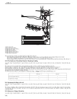
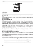
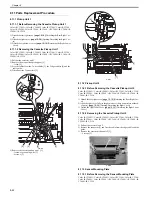
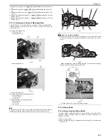
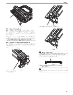
8.11.11.2 Removing Cassette Paper Sensor
0014-0698
Color iR C3380G / Color iR C2880G / Color iR C3380i / Color iR C3380 /
Color iR C2880i / Color iR C2880 / iR C3480 / iR C3480i / iR C3080 / iR
C3080i / iR C2550
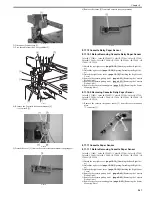
1) Remove the cassette paper sensor [2] from the sensor mounting plate.
- 1 connector [1]
F-8-76
8.11.12 Cassette Paper Level Sensor (A/B)
8.11.12.1 Before Removing Cassette Paper Level Sensor
(A/B)
0014-0705
Color iR C3380G / Color iR C2880G / Color iR C3380i / Color iR C3380 /
Color iR C2880i / Color iR C2880 / iR C3480 / iR C3480i / iR C3080 / iR
C3080i / iR C2550
1) Detach the rear right cover.
[Detaching the Rear Right Cov-
er]
2) Detach the right cover.
[Opening/Detaching the Right Cov-
er]
3) Detach the right lower cover.
[Detaching the Right Lower
Cover]
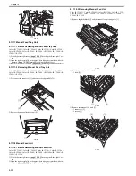
4) Remove the cassette pickup unit 2.
Pickup Unit 2]
5) Remove the cassette pickup unit 1.
Pickup Unit 1]
6) Remove the sensor mounting plate.
[Removing the Sensor
Mounting Plate]
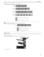
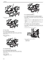
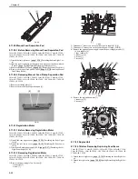
8.11.12.2 Removing Cassette Paper Level Sensor (A/B)
0014-0706
Color iR C3380G / Color iR C2880G / Color iR C3380i / Color iR C3380 /
Color iR C2880i / Color iR C2880 / iR C3480 / iR C3480i / iR C3080 / iR
C3080i / iR C2550
1) Remove the cassette paper level sensor (A/B) [2] from the sensor mount-
ing plate.
- 1 connector each [1]
F-8-77
8.11.13 Slide Resistor
8.11.13.1 Before Removing Slide Resistor
0014-1176
Color iR C3380G / Color iR C2880G / Color iR C3380i / Color iR C3380 /
Color iR C2880i / Color iR C2880 / iR C3480 / iR C3480i / iR C3080 / iR
C3080i / iR C2550
1) Detach the rear right cover.
[Detaching the Rear Right Cov-
er]
2) Open the right cover fully (to the point where it does not interfere with oth-
er parts).
[Opening/Detaching the Right Cover]
3) Remove the manual feed unit.
[Removing Manual Feed Unit]
4) Remove the manual feed tray unit.
[Removing Manual Feed
Tray Unit]
8.11.13.2 Removing Slide Resistor
0014-1178
Color iR C3380G / Color iR C2880G / Color iR C3380i / Color iR C3380 /
Color iR C2880i / Color iR C2880 / iR C3480 / iR C3480i / iR C3080 / iR
C3080i / iR C2550
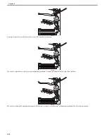
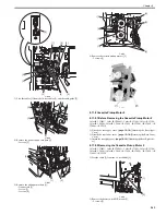
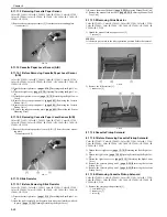
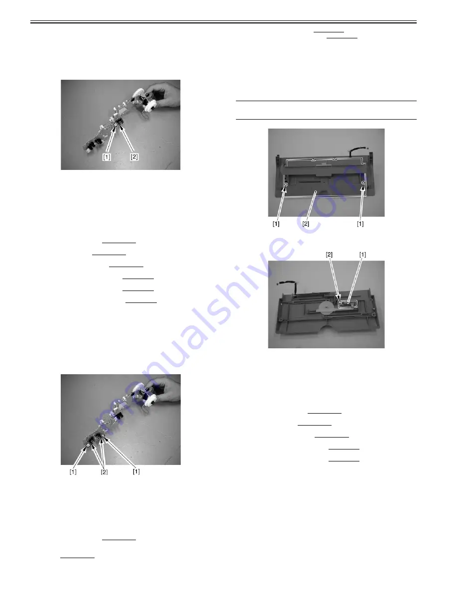
1) Detach the manual feed tray upper cover [2].
- 2 screws [1]
MEMO:
It is better to put a mark to the side registration position before the removal.
F-8-78
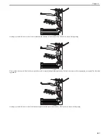
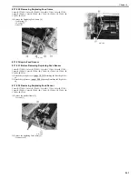
2) Remove the slide resistor [1].
- 1 connector [2]
F-8-79
8.11.14 Cassette Pickup Solenoid
8.11.14.1 Before Removing Cassette Pickup Solenoid
0014-1183
Color iR C3380G / Color iR C2880G / Color iR C3380i / Color iR C3380 /
Color iR C2880i / Color iR C2880 / iR C3480 / iR C3480i / iR C3080 / iR
C3080i / iR C2550
1) Detach the rear right cover.
[Detaching the Rear Right Cov-
er]
2) Detach the right cover.
[Opening/Detaching the Right Cov-
er]
3) Detach the right lower cover.
[Detaching the Right Lower
Cover]
4) Remove the cassette pickup unit 2.
[Removing the Cassette
Pickup Unit 2]
5) Remove the cassette pickup unit 1.
[Removing the Cassette
Pickup Unit 1]
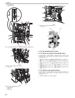
8.11.14.2 Removing Cassette Pickup Solenoid
0014-1188
Color iR C3380G / Color iR C2880G / Color iR C3380i / Color iR C3380 /
Color iR C2880i / Color iR C2880 / iR C3480 / iR C3480i / iR C3080 / iR
C3080i / iR C2550
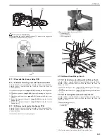
1) Remove the cassette pickup solenoid [1].
- 1 wire saddle [2]
- 1 connector [3]
- 1 screw [4]
Содержание CiRC2550
Страница 2: ......
Страница 27: ...Chapter 1 Introduction ...
Страница 28: ......
Страница 47: ...Chapter 1 1 18 F 1 14 ON OFF ON OFF ...
Страница 70: ...Chapter 1 1 41 5 Turn on the main power switch ...
Страница 79: ...Chapter 2 Installation ...
Страница 80: ......
Страница 85: ...Chapter 2 2 3 Not available in some regions ...
Страница 134: ...Chapter 3 Basic Operation ...
Страница 135: ......
Страница 137: ......
Страница 143: ...Chapter 4 Main Controller ...
Страница 144: ......
Страница 152: ...Chapter 4 4 6 F 4 6 CPU HDD ROM access to the program at time of execution ...
Страница 171: ...Chapter 5 Original Exposure System ...
Страница 172: ......
Страница 203: ...Chapter 6 Laser Exposure ...
Страница 204: ......
Страница 206: ......
Страница 220: ...Chapter 7 Image Formation ...
Страница 221: ......
Страница 277: ...Chapter 8 Pickup Feeding System ...
Страница 278: ......
Страница 282: ......
Страница 336: ...Chapter 9 Fixing System ...
Страница 337: ......
Страница 339: ......
Страница 357: ...Chapter 10 Externals and Controls ...
Страница 358: ......
Страница 362: ......
Страница 366: ...Chapter 10 10 4 F 10 2 F 10 3 FM1 FM2 FM5 FM8 FM11 FM4 FM3 FM6 FM7 FM9 FM10 ...
Страница 375: ...Chapter 10 10 13 F 10 10 2 Remove the check mark from SNMP Status Enabled ...
Страница 376: ...Chapter 10 10 14 F 10 11 ...
Страница 402: ...Chapter 11 MEAP ...
Страница 403: ......
Страница 405: ......
Страница 452: ...Chapter 12 RDS ...
Страница 453: ......
Страница 455: ......
Страница 464: ...Chapter 13 Maintenance and Inspection ...
Страница 465: ......
Страница 467: ......
Страница 469: ...Chapter 13 13 2 F 13 1 8 9 1 2 3 3 5 6 7 10 11 12 13 14 4 ...
Страница 474: ...Chapter 14 Standards and Adjustments ...
Страница 475: ......
Страница 477: ......
Страница 485: ......
Страница 486: ...Chapter 15 Correcting Faulty Images ...
Страница 487: ......
Страница 495: ...Chapter 15 15 4 F 15 2 COLOR M 1 COLOR Y C K 0 ...
Страница 569: ...Chapter 15 15 78 F 15 82 J102 J107 J103 J108 J101 J109 J106 J112 J115 J113 J114 J104 J105 ...
Страница 570: ...Chapter 16 Self Diagnosis ...
Страница 571: ......
Страница 573: ......
Страница 600: ...Chapter 17 Service Mode ...
Страница 601: ......
Страница 603: ......
Страница 712: ...Chapter 18 Upgrading ...
Страница 713: ......
Страница 715: ......
Страница 746: ...Chapter 19 Service Tools ...
Страница 747: ......
Страница 748: ...Contents Contents 19 1 Service Tools 19 1 19 1 1 Special Tools 19 1 19 1 2 Solvents and Oils 19 2 ...
Страница 749: ......
Страница 752: ...APPENDIX ...
Страница 774: ......


