


Chapter 6
6-3
5) The resulting laser beam hits the 6-facet mirror, which is rotating at a specific speed.
6) The laser beam then is reflected by the 6-facet mirror, and is moved to the imaging lens and the reflecting mirror found in front of the mirror to reach the
surface of the photosensitive drum.
7) As the 6-facet mirror rotates at a specific speed, the laser beam scans the surface of the photosensitive drum accordingly.
8) As the 6-facet mirror rotates and, as a result, the laser beams scan the surface of the photosensitive drum at a specific speed, a static image of multiple colors
is formed on the drum surface.
1 : The machine's BD circuit is found on its CBk driver PCB, and the BD signal occurs in keeping with the activation of the laser diode of the Bk driver.
2 : 1-Polygon 4-Laser Method
The term refers to a method in which a single polygon mirror is used for 4 laser beams. There are 4 laser diodes, the beams of which are directed to a multiple-facet
mirror mounted on a single scanner motor. The method inherently brings about a reduction in space.
6.2 Various Control
6.2.1 Controlling the Laser Activation Timing
6.2.1.1 Turning On and Off the Laser Light
0013-8532
Color iR C3380G / Color iR C2880G / Color iR C3380i / Color iR C3380 / Color iR C2880i / Color iR C2880 / iR C3480 / iR C3480i / iR C3080 / iR C3080i / iR
C2550
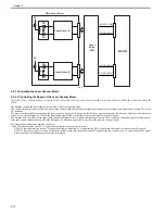
The laser light goes on and off when the laser diode of the laser driver PCB goes on and off at a specific intensity. The machine's laser driver PCB consists of 2
PCBs (Y/M laser driver PCB, C/Bk laser driver PCB), each with 2 systems of driver circuitry. The circuit turns on and off the laser light of individual colors ac-
cording to the combination of laser control signals (LC_CTL0/LC_CTL1) coming from the DC controller.
T-6-5
F-6-2
[1] Y/M laser driver
[2] Y laser control signal
[3] M laser control signal
[4] C laser control signal
[5] Bk laser control signal
[6] C/Bk laser driver
Laser control signal
Operation
Laser state
LC_CTL0
LC_CTL1
0
0
forced off
OFF
0
1
APC
ON
1
0
printing
video signal input permitted
1
1
standby
OFF
[2] [3]
[4]
[5]
[1]
[6]
D-CON
Содержание CiRC2550
Страница 2: ......
Страница 27: ...Chapter 1 Introduction ...
Страница 28: ......
Страница 47: ...Chapter 1 1 18 F 1 14 ON OFF ON OFF ...
Страница 70: ...Chapter 1 1 41 5 Turn on the main power switch ...
Страница 79: ...Chapter 2 Installation ...
Страница 80: ......
Страница 85: ...Chapter 2 2 3 Not available in some regions ...
Страница 134: ...Chapter 3 Basic Operation ...
Страница 135: ......
Страница 137: ......
Страница 143: ...Chapter 4 Main Controller ...
Страница 144: ......
Страница 152: ...Chapter 4 4 6 F 4 6 CPU HDD ROM access to the program at time of execution ...
Страница 171: ...Chapter 5 Original Exposure System ...
Страница 172: ......
Страница 203: ...Chapter 6 Laser Exposure ...
Страница 204: ......
Страница 206: ......
Страница 220: ...Chapter 7 Image Formation ...
Страница 221: ......
Страница 277: ...Chapter 8 Pickup Feeding System ...
Страница 278: ......
Страница 282: ......
Страница 336: ...Chapter 9 Fixing System ...
Страница 337: ......
Страница 339: ......
Страница 357: ...Chapter 10 Externals and Controls ...
Страница 358: ......
Страница 362: ......
Страница 366: ...Chapter 10 10 4 F 10 2 F 10 3 FM1 FM2 FM5 FM8 FM11 FM4 FM3 FM6 FM7 FM9 FM10 ...
Страница 375: ...Chapter 10 10 13 F 10 10 2 Remove the check mark from SNMP Status Enabled ...
Страница 376: ...Chapter 10 10 14 F 10 11 ...
Страница 402: ...Chapter 11 MEAP ...
Страница 403: ......
Страница 405: ......
Страница 452: ...Chapter 12 RDS ...
Страница 453: ......
Страница 455: ......
Страница 464: ...Chapter 13 Maintenance and Inspection ...
Страница 465: ......
Страница 467: ......
Страница 469: ...Chapter 13 13 2 F 13 1 8 9 1 2 3 3 5 6 7 10 11 12 13 14 4 ...
Страница 474: ...Chapter 14 Standards and Adjustments ...
Страница 475: ......
Страница 477: ......
Страница 485: ......
Страница 486: ...Chapter 15 Correcting Faulty Images ...
Страница 487: ......
Страница 495: ...Chapter 15 15 4 F 15 2 COLOR M 1 COLOR Y C K 0 ...
Страница 569: ...Chapter 15 15 78 F 15 82 J102 J107 J103 J108 J101 J109 J106 J112 J115 J113 J114 J104 J105 ...
Страница 570: ...Chapter 16 Self Diagnosis ...
Страница 571: ......
Страница 573: ......
Страница 600: ...Chapter 17 Service Mode ...
Страница 601: ......
Страница 603: ......
Страница 712: ...Chapter 18 Upgrading ...
Страница 713: ......
Страница 715: ......
Страница 746: ...Chapter 19 Service Tools ...
Страница 747: ......
Страница 748: ...Contents Contents 19 1 Service Tools 19 1 19 1 1 Special Tools 19 1 19 1 2 Solvents and Oils 19 2 ...
Страница 749: ......
Страница 752: ...APPENDIX ...
Страница 774: ......


