


16
1. Click OK, the project is now added and displayed
in the DataXport Design window.
Running the project
2.
Select “Run Project” from the “Actions” menu,
(Save and name your project) DataXport begins
exporting the requested data via your defined port
and defined schedules.
3.
You can also cause DataXport to enter “Run”
mode whenever the project is opened by selecting
that option from the “Actions” menu.
4.
You can also force DataXport to enter “Run” mode
by selecting “Run Project” and then clicking the
“Force Call” button.
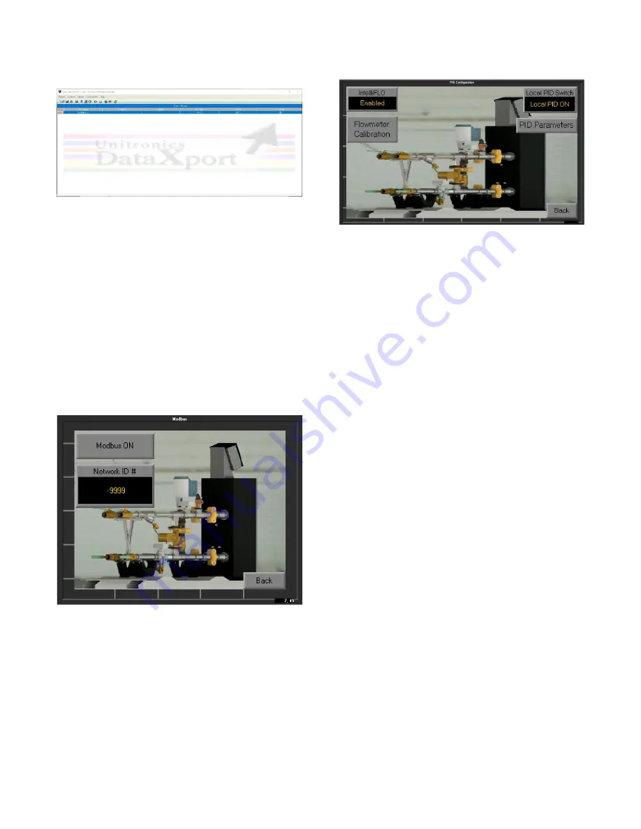
5.2.3.3
– <Modbus>
The user can assign a network ID or slave address to
DynaFLO
’s controller by pressing <Network ID #> and
inserting a number.
When <Modbus ON/OFF> switch turns ON it opens Port 2
on DynaFLO
’s controller and sets the controller as a
Modbus Slave with the following parameters:
Baud Rate: 19200
Data Bits: 8
Parity: None
Stop Bits: 1
Standard: RS485
A Modbus Master at this point can send commands to
DynaFLO
’s controller based on section 5.2.1 and the
Modbus Mapping table in section 5.1.
5.2.3.4
– <PID Configuration and IntelliFLO>
The <Local PID ON/OFF> switch turns the built-in PID loop
in DynaFLO
’s controller ON and OFF. This could become
handy for troubleshooting or to restart the local PID loop in
case it got stuck in what is called an integral wind down or
an integral windup; which may happen in case <Setpoint>
is suddenly changed by the user by a large amount.
PID Parameters> will take the user to a display that allows
the user to change the Proportional, Integral and Derivative
parameters that govern the performance of the local built-in
PID loop. However these parameters have been fine-tuned
through extensive testing specifically for DynaFLO and
changing these parameters are not recommended as the
performance of the local PID loop is very sensitive to a
change in these parameters. Therefore access to this
screen requires factory level password which may only be
provided in special situations.
The <IntelliFLO> button enables/disables the IntelliFLO
(Patent pending) feature. Upon enabling IntelliFLO, the
controller proactively adjusts the actuator upon sensing
rapid DHW load changes to prevent temperature spikes. If
DHW flow is stable and IntelliFLO is still enabled, the main
fine-tuned feedback PID loop is still in charge of hundred
percent of the control. IntelliFLO is smart and automatic in
a sense that it is always watching the DHW load and it only
takes over control of the actuator in case there is a sudden
flow change. Once flow is stabilized again, IntelliFLO gives
the control back to the main feedback PID loop. As a result
there are no parameters to be adjusted by the installer or
the user, only to enable or disable the entire feature.
If your DynaFLO is not equipped with the optional IntelliFLO
technology, <IntelliFLO
> should be switched to “Disabled”.
Under <Flowmeter Calibration>, a constant (K Factor) can
be adjusted to adjust the IntelliFLO
’s flowmeter reading.
However factory should be consulted before changing this
constant as it is recommended to leave the constant
unchanged.
Содержание DynaFLO DOWB-1
Страница 2: ......
Страница 25: ...22 Appendix B Electrical Schematics DynaFLO ...
Страница 27: ...24 ...


