


TX321 Transmitter
6
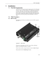
2.
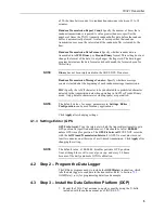
Install elements to boom.
When attaching elements to the boom, make sure to place them
such that the number of grooves on the element equals the number
of dimples on the boom. For example, place the element with four
grooves at the spot on the boom with four dimples, and so forth.
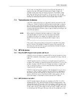
FIGURE 4-3. Yagi antenna
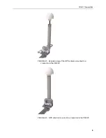
3.
Aim the Yagi antenna at the spacecraft; azimuth and elevation angle
positions are included on the bracket label. The
Alignment
tab in
DevConfig
can be used to determine the correct coordinates for the
azimuth and elevation (see FIGURE
). From the
Align to Satellite
list,
select either the
East
or the
West
satellite, type the
Transmitter
Latitude
,
Transmitter
Longitude
,
Transmitter
Altitude
, and the
Magnetic
Declination
. The correct angles are then displayed in the lower panel.
(p. 2)
, for information
about accessing
DevConfig
. The transmitter internal GPS can be
used to acquire azimuth and elevation information. To use the
internal GPS device, connect the GPS antenna (see FIGURE
).
The information is listed on the GPS tab of
DevConfig
.
NOTE
NOTE
Содержание TX321
Страница 1: ...TX321 Transmitter Revision 5 19 Copyright 2000 2019 Campbell Scientific ...
Страница 2: ......
Страница 4: ......
Страница 6: ......
Страница 8: ......
Страница 46: ......
Страница 48: ......
Страница 56: ......
Страница 82: ......
Страница 84: ...AppendixE Meteosat F 2 FIGURE F 2 DCPRS and CGMS certificate ...
Страница 85: ...AppendixE Meteosat F 3 FIGURE F 3 EUMETSAT certificate ...