background image

TDR200-Based Time-Domain Reflectometry System 

17 

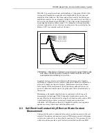
FIGURE 

8-1

 presents waveforms collected from a 3-rod probe (CS610) with 

varying cable lengths. Increasing the cable length affects the rise time and 

amplitude of the reflection. The slopes and extrema used by the data logger 

algorithm to analyze the waveform are shifted by the cable losses resulting in 

an error. For the data shown in FIGURE 

8-1

, the water content measurement 

error using the 66-met

re

 cable is about 1.5% volumetric water content when 

electrical conductivity is low. However, in saline soils, the error is higher. See 

Bilskie (1997) for complete results of the study. 

FIGURE 8-1.  Waveforms collected in a sandy loam using CS610 probe 

with RG8 connecting cable. Volumetric water content is 24% and 

bulk electrical conductivity is 0.3 dS m

–1

In general, water content is overestimated with increasing cable length. A 

calibration of volumetric water content with apparent dielectric constant for a 

given cable length can improve accuracy. Measurement precision at longer 

cable lengths will be maintained if the soil electrical conductivity does not 

prevent a reflection from the end of the probe rods. This is discussed later in 

this section. 

Minimizing cable lengths should always be considered in the design of a 

measurement system using TDR. If long cable lengths are necessary, the 

adverse effects can be minimized by using low attenuation cable such as RG8. 

Careful probe design ensures correct probe impedance giving robust 

reflections. All TDR probes offered by Campbell Scientific are designed to 

optimize accuracy when longer cable lengths are used. 

8.3  Soil Electrical Conductivity Effect on Water Content 

Measurement 

The signal at the probe is attenuated when ionic conduction occurs in the soil 

solution. This inherent attenuation is used in TDR measurements to determine 

soil electrical conductivity as described by equation [5]. The presence of ions 

in the soil solution provides a path for electrical conduction between TDR 

16  met

re

  cable


26  met

re

  cable


45  met

re

  cable


66 met

re

 cable

Содержание TDR200

Страница 1: ...TDR200 TDR200 Based Time Domain Reflectometry System Revision 8 19 Copyright 2016 2019 Campbell Scientific Product Manual...

Страница 2: ......

Страница 3: ...under guarantee or not Please state the faults as clearly as possible and if the product is out of the guarantee period it should be accompanied by a purchase order Quotations for repairs can be give...

Страница 4: ......

Страница 5: ...digital cell phones and aerials may also not be applicable according to your locality Some brackets shields and enclosure options including wiring are not sold as standard items in the European marke...

Страница 6: ......

Страница 7: ...beginning work Wear a hardhat and eye protection and take other appropriate safety precautions while working on or around tripods and towers Do not climb tripods or towers at any time and prohibit cl...

Страница 8: ......

Страница 9: ...er Control 9 7 1 1 Data Logger 10 7 1 2 TDR200 10 7 1 3 SDM8X50 10 7 1 4 Power Supply 11 7 1 4 1 Grounding 11 7 1 5 SDM Communication 12 7 1 6 ENCTDR100 12 7 1 6 1 Mounting Equipment in ENCTDR100 12 7...

Страница 10: ...inal strip adapters for connections to battery 11 7 3 ENCTDR100 with SDM8X50 PS150 TDR200 and CR1000 13 8 1 Waveforms collected in a sandy loam using CS610 probe with RG8 connecting cable Volumetric w...

Страница 11: ...re rod of TDR probes connected to the TDR200 The maximum recommended total length of all synchronous device for measurement SDM cables should not exceed 500 feet Longer total lengths cause unreliable...

Страница 12: ...DR100 Packing List The following are included with an ENCTDR100 Enclosure Supply Kit that includes desiccant packs humidity indicator cable ties putty and mounting hardware ENCTDR100 Enclosure Ground...

Страница 13: ...e Serial Port 7 Typically use the default baud rate of 57 600 The SDM Address must match the address of the TDR200 For Noise Rejection Frequency select 50 Hz or 60 Hz rejection if the system is near A...

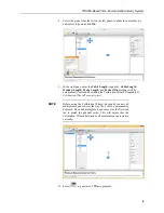
Страница 14: ...settings will be automatically entered when using the Calibration Wizard Appendix B Calibration Wizard Tutorial p B 1 Before using the Calibration Wizard physically connect all multiplexers and sensor...

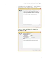
Страница 15: ...try System 5 11 Enter a name for the CRBasic program Click to specify where to save the program and what type of program to generate Press Next 12 Select what is measured and stored as well as time in...

Страница 16: ...parate strain relief bracket for the coaxial cables Both the multiplexer housing and the strain relief bracket have holes drilled at a 1 inch spacing This allows the SDM8X50 to be mounted to a wall or...

Страница 17: ...s the TDR200 and other system components from weather condensing humidity and dust 6 Specifications Features Uses compact low cost TDR200 with performance features that match or exceed other available...

Страница 18: ...120 mA 1 mA Temperature range 40 to 85 C Height 10 7 cm 4 2 in Width 5 1 cm 2 0 in Length 21 6 cm 8 5 in Weight 0 79 kg 1 75 lb 6 2 Electromagnetic Compatibility The TDR200 is compliant with performan...

Страница 19: ...e includes a bracket for mounting to a tripod a tower or a 1 0 in to 1 25 in IPS Schedule 40 pipe Weight 4 4 kg 9 8 lb Enclosure Outside Dimensions with Mounts 40 x 29 x 17 5 cm 16 x 12 x 7 in Enclosu...

Страница 20: ...rical algorithms for measuring volumetric water content or electrical conductivity The TDR200 communicates with the data logger using SDM protocol or with a computer using PC TDR and serial communicat...

Страница 21: ...er the TDR200 This practice reduces power consumption and resets the TDR200 which provides automatic recovery from system malfunctions and reduces loss of measurement data when a problem exists The SW...

Страница 22: ...l cables are needed to connect different levels of multiplexers use the CABLE5CBL L cable The maximum total length of all SDM cables should not exceed 500 feet to ensure reliable communication between...

Страница 23: ...g the waveguide will occur where there are impedance changes The impedance value is related to the geometrical configuration of the probe size and spacing of rods and also is inversely related to the...

Страница 24: ...orted by PC TDR program generator CRBasic is included in PC400 or LoggerNet software The TDR200 CRBasic instruction is used to program the TDR200 Programming basics are provided in the following secti...

Страница 25: ...ts filtering and averaging used to improve measurements in noisy environments and the algorithms used to calculate the measurements 8 1 TDR Principles The travel time for a pulsed electromagnetic sign...

Страница 26: ...nding the waveguide the amplitude of the reflected voltage is dependent on electrical conduction of the applied signal between probe rods The presence of free ions in the soil solution causes attenuat...

Страница 27: ...dielectric constant for a given cable length can improve accuracy Measurement precision at longer cable lengths will be maintained if the soil electrical conductivity does not prevent a reflection fr...

Страница 28: ...ws data for solution with high electrical conductivity FIGURE 8 2 Waveforms collected in a sandy loam using CS610 probe with RG8 connecting cable Volumetric water content values are 0 10 0 16 0 18 0 2...

Страница 29: ...lue two values prior to the point of interest the actual measured point of interest and the two values after that point Each of those points is weighted with the closer points having more weight than...

Страница 30: ...re used for the reflected signal Each of these values are normalized by a value collected from inside the TDR200 A brief description of the algorithm is presented here 1 Begin at waveform data point 4...

Страница 31: ...Processes 7 45 49 Ledieu J P De Ridder P De Clerck and S Dautrebande 1986 A method of measuring soil moisture by time domain reflectometry J Hydrol 88 319 328 Or D S B Jones J R Van Shaar S Humphries...

Страница 32: ......

Страница 33: ...635 has 2 metre cable and a 3 metre window Public CS635_LaL Public CS635_VWC Public CS635_WaveFormValues 1013 Topp Equation Dielectric Constants const a0 0 053 const a1 0 0292 const a2 0 00055 Const a...

Страница 34: ......

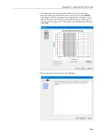
Страница 35: ...t Before using the Calibration Wizard physically connect all multiplexers and sensors the way they will be permanently deployed This will ensure that the Calibration Wizard determines all measurement...

Страница 36: ...lighted region click on the highlighted area in the wizard window and move or scale the region to encompass the entire portion of the probe If it is difficult to find the probe or the probe was not en...

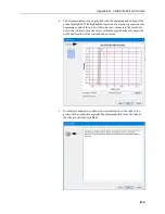
Страница 37: ...be reflections are not properly found click Refresh and attempt to find the beginning and end again If the waveform is noisy increase the number of averages or adjust the filtering level Section 8 4 F...

Страница 38: ...sent the beginning or end of the probe either enter new values into the text boxes below the window or use the cursor within the graph window to adjust the width and location of the start and end posi...

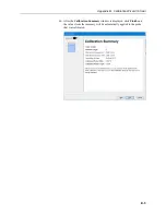
Страница 39: ...pendix B Calibration Wizard Tutorial B 5 10 After the Calibration Summary window is displayed click Finish and the values from the summary will be automatically applied to the probe that was calibrate...

Страница 40: ......

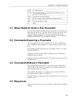
Страница 41: ...ommand list SVP Set Vp Value SNA Set Number of Averages SNP Set Number of Points SDI Set Distance Cable Length SWL Set Window Length SPL Set Probe Length SPO Set Probe Offset SCC Set Probe Cell Consta...

Страница 42: ...The commands SVP SNA SNP SDI SWL SPL SPO SCC SREJ SFIL SLAA and SMUX require a parameter For these commands usage is of this form Command space ASCII parameter r n For example SPL 0 3 r n will set the...

Страница 43: ...ses are returned by the sensor in response to commands that set a parameter in the device Ack responses begin with a CR and LF and are of the form r n space command For example the response to SPL 0 3...

Страница 44: ...et Length Apparent Algorithm Usage SLAA space value r n range of value 0 2 Response r n space SLAA SMUX Set SDMX50 channel Usage SMUX space value r n value address 1 to 15 10 channel 1 to 8 Response r...

Страница 45: ...an ASCII representation of a floating point value 4 decimal places GCO Acquire a new Waveform and return Electrical Conductivity value Usage GCO r n Response r n f ffff where f ffff is an ASCII repres...

Страница 46: ...a Waveform Usage GWA r n Response r n NNNN space f ffff r n NNNN space f ffff r n NNNN space f ffff etc where NNNN is the 4 digit width point number and f ffff is an ASCII representation of the assoc...

Страница 47: ......

Страница 48: ...cc Website www campbellsci cc France Location Vincennes France Phone 0033 0 1 56 45 15 20 Email info campbellsci fr Website www campbellsci fr Germany Location Bremen Germany Phone 49 0 421 460974 0...

Отзывы: