Appendix D. Distance vs. Antenna Gain, Terrain, and Other Factors
D-3
If losses due to obstructions in the line-of-sight path of
propagation are anticipated and a highly reliable link is required,
it is strongly recommended that a professional path study be
conducted before proceeding with the installation.
By algebraically summing the transmitters output power with the links gains
and losses, the signal power at the receiver’s input (Prx) can be estimated. If
Prx is greater than the receiver’s sensitivity (
−
108 dBm for the RF451), a
connection is possible. The amount by which Prx exceeds the receiver’s
sensitivity is the fade margin. A minimum fade margin of 10 dB is
recommended for a reliable link.
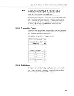
D.2.3 Transmitter Power
Transmitter output power is often expressed in dBm, which is a decibel power
rating relative to 1 mW. The conversion formula between transmitter power in
mW (Pt) and transmitter power in dBm (Ptx) is:
Ptx (in dBm) = 10 log (Pt) with Pt expressed in mW
TABLE D-1. Transmitter Power
Transmitter Power (Pt)
(milliWatts)
Ptx
dBm
1
0
5
7
10 (RF451 minimum)
10
50
17
100
20
250
24
1000 (RF451 maximum)
30
5000
37
D.2.4 Cable Loss
Cable loss is a function of cable type, length, and frequency and is usually
specified as attenuation (dB) per 100 ft. of cable at a given frequency. Using a
low loss cable becomes more important as the cable run distances increase.
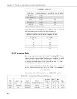
Here are some typical cable types and their properties:
NOTE
Содержание RF451
Страница 2: ......
Страница 6: ......
Страница 10: ...Table of Contents iv ...
Страница 34: ...RF451 Spread Spectrum Radio 24 ...
Страница 36: ......
Страница 46: ...Appendix B Installation Scenarios B 10 ...
Страница 58: ...Appendix D Distance vs Antenna Gain Terrain and Other Factors D 10 ...
Страница 60: ......
Страница 61: ......


