background image

Appendix B.  Installation Scenarios 

B-2 


FIGURE B-2.  DevConfig Screen Showing Master Radio Settings for 

Example 1 

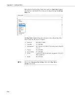
The 

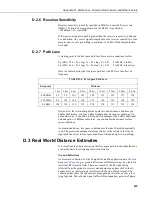
Network Map

 in the 

LoggerNet Setup

 screen should look something like 

this:  


B.2  Example 2: PC-to-RF Network with Repeater 

In this example, the master radio is connected to a PC running 

LoggerNet

 (see 

FIGURE 

B-3

). Slave radios are connected to CR1000s in the field. One slave 

radio, also connected to a CR1000, is used as a repeater to go around an 

obstacle such as a hill. To take advantage of the low power mode, those 

devices that are NOT repeaters should be configured as multi-point slaves and 

not as multi-point slave/repeaters. In this configuration, it may be desirable to 

use an external omnidirectional antenna at the repeater. 

Note that when a repeater is used, the RF throughput is cut in half. However, 

when more than one repeater is used, there is no further degradation in the RF 

throughput of the link. Throughput is the rate at which data is sent or received. 

Reducing throughput means less data can be transmitted in a specified amount 

of time.  

Remember, each datalogger must have a unique PakBus address.  

Содержание RF451

Страница 1: ...INSTRUCTION MANUAL RF451 Spread Spectrum Radio Revision 3 18 C o p y r i g h t 2 0 0 1 2 0 1 8 C a m p b e l l S c i e n t i f i c I n c ...

Страница 2: ......

Страница 3: ...ducts to CSI CSI will return such Products by surface carrier prepaid within the continental United States of America To all other locations CSI will return such Products best way CIP port of entry per Incoterms 2010 This warranty shall not apply to any Products which have been subjected to modification misuse neglect improper service accidents of nature or shipping damage This warranty is in lieu...

Страница 4: ...ping address is CAMPBELL SCIENTIFIC INC RMA _____ 815 West 1800 North Logan Utah 84321 1784 For all returns the customer must fill out a Statement of Product Cleanliness and Decontamination form and comply with the requirements specified in it The form is available from our website at www campbellsci com repair A completed form must be either emailed to repair campbellsci com or faxed to 435 227 9...

Страница 5: ...e beginning work Wear a hardhat and eye protection and take other appropriate safety precautions while working on or around tripods and towers Do not climb tripods or towers at any time and prohibit climbing by other persons Take reasonable precautions to secure tripod and tower sites from trespassers Use only manufacturer recommended parts materials and tools Utility and Electrical You can be kil...

Страница 6: ......

Страница 7: ... 2 2 SDC Address 9 7 2 3 Baud Rate 9 7 2 4 Radio Operation Mode 9 7 2 4 1 Operation Mode Description 9 7 2 5 Network ID 10 7 2 6 Frequency Key 10 7 2 7 Repeater Frequency Key 10 7 2 8 Transmit Power 11 7 2 9 Low Power Mode 12 7 2 10 SubNet ID 13 7 2 11 Radio ID 13 7 3 Master Radio 14 7 4 Slave 14 7 5 Repeater 15 7 6 Location of the Transceivers 16 7 7 Power Considerations 16 7 8 LoggerNet Software...

Страница 8: ...udget D 2 D 2 3 Transmitter Power D 3 D 2 4 Cable Loss D 3 D 2 5 Antenna Gain D 4 D 2 6 Receiver Sensitivity D 5 D 2 7 Path Loss D 5 D 3 Real World Distance Estimates D 5 D 4 Examples D 7 E RF451s with RF401A or CR206 X in the Same Network E 1 Figures 5 1 Simplest Form of a Multi Point Network 3 7 1 Startup DevConfig Screen for Configuring the RF451 5 7 2 DevConfig Screen Showing the RF451 Setting...

Страница 9: ...Tables 7 1 Transmit Power Settings 12 7 2 Low Power Mode Settings 12 7 3 Power Requirements at 12 Vdc 16 9 1 Status LED 21 9 2 TX RX LED 22 B 1 RF451 Settings for Example 1 B 1 B 2 RF451 Settings for Example 2 B 3 B 3 RF451 Settings for Example 3 B 6 B 4 RF451 Settings for Example 4 B 7 D 1 Transmitter Power D 3 D 2 Cable Loss D 4 D 3 LMR 195 Cable Loss vs Length 900 MHz D 4 D 4 Antenna Gain of Re...

Страница 10: ...Table of Contents iv ...

Страница 11: ...ion to comply with local laws and to avoid interference with other RF installations such as cellular services Available hop table versions are listed in the Device Configuration Utility DevConfig Settings Editor for the RF451 Hop table versions include North America default Australia New Zealand Taiwan Brazil International and Notch custom See Appendix C Settings Editor p C 1 for more information ...

Страница 12: ... above Keep the remaining settings at their defaults See note below regarding repeaters 6 Master Radio Using DevConfig set the Radio Operation Mode to Multi Point Master Set the Network ID to the number decided upon in step 2 above Set the Frequency Key to the number decided upon in step 3 above Set the Radio ID to the PakBus Address assigned in step 1 above If the master radio will be at PC runni...

Страница 13: ...t a set number of times determined by the user The receiving transceiver slave or repeater will accept the first packet received with the correct signature 32 bit CRC However the packet is not acknowledged On the return trip to the master all packets sent are acknowledged or retransmitted until they are acknowledged Therefore the return link in a multi point network is generally very robust Tradit...

Страница 14: ...to 111 user selectable Hopping Bands 7 user selectable Frequency Zones 16 zones Receive Sensitivity 108 dBm at 115 2 kbps for 10 4 bit error rate 103 dBm at 153 6 kbps for 10 4 bit error rate IF Selectivity 40 dB at fc 230 kHz RF Selectivity 60 dB at 896 MHz 935 MHz Dynamic Range 10 dBm 3rd Order Intercept Point at Input Connector Data Transmission Error Detection 32 bit CRC retransmit on error Da...

Страница 15: ...Utility DevConfig software tool that comes with LoggerNet see FIGURE 7 1 DevConfig is also available for free from the Campbell Scientific website The following general procedure is used to configure an RF451 radio via DevConfig 1 Launch DevConfig from the LoggerNet toolbar by double clicking the icon on the Windows Desktop or through the Windows Start Menu Start All Programs LoggerNet Device Conf...

Страница 16: ...lled before you can connect to the radio via USB 4 With the USB device driver installation complete connect the supplied USB cable between the USB port on your computer and the USB port on the radio 5 Select the correct COM port for serial communications over USB with the radio using DevConfig It should be listed in the dialog as RF451 COM where is the COM port number It may take a few seconds for...

Страница 17: ...ld be used by experienced FreeWave Radio users only New operating systems for the Campbell Scientific board are loaded through the Send OS tab DevConfig makes applying the same settings to multiple devices easy Once settings are configured for one device click Apply a summary screen similar to FIGURE 7 3 will be shown Click Save to save a configuration file This file can then be used to load the s...

Страница 18: ...nfigurations 7 2 1 Active Interface Specify the interface that will be used for normal operations The following active interfaces are available RS 232 The RS 232 port is used at the Baud Rate selected CS I O SDC The CS I O port is used and configured as SDC at the SDC Address selected CS I O ME Master The CS I O port is used and configured for direct connection to a CSI COM200 COM210 COM220 or oth...

Страница 19: ...remember that a number of parameters are controlled by the settings in the master Also radio network diagnostics can only be accessed at the master radio Therefore we suggest you deploy the master on the communications end where it will be easier to access For a datalogger PakBus network the multi point radio modes should be used For other configurations the Operation Mode will need to be set thro...

Страница 20: ... point to point networks A slave will link with the first master or repeater that it hears with a matching Network ID Assigning a unique Network ID will reduce the chance a radio in your network links with another unrelated network in the same RF area If necessary the Network ID function can be used in conjunction with the SubNet ID feature 7 2 6 Frequency Key The Frequency Key determines the freq...

Страница 21: ...er Power Antenna Gain Cable Losses all in dB or dBm Radio installations should be performed by a professional It is very important that the transmit power level selected and the gain of the attached antenna do not exceed the maximum allowed ERP permitted by local regulations Regulations vary by country and region As the equipment owner you are responsible for making sure that your installation and...

Страница 22: ...ceiver sleeps 2 out of 3 slots and so on TABLE 7 2 shows the changes at different Low Power Mode settings The actual current draw depends on many factors The table below gives only a qualitative indication of supply current savings A low number reduces latency and a high number reduces current consumption An optimum setting balancing latency and power savings is 2 or 3 TABLE 7 2 Low Power Mode Set...

Страница 23: ...nsmit is 15 which disables SubNetwork functions For the master this setting 15 causes the master to actually use 0 So if the SubNet ID is to be used the downstream radios that need to connect to the master will need their Receive SubNet ID set to 0 Changing these settings on the master is not recommended under normal circumstances The Receive SubNet ID on the master has no effect on the network If...

Страница 24: ...r in multi point mode This mode allows one master transceiver to simultaneously be in communication with numerous slaves and repeaters A multi point master communicates only with other transceivers designated as multi point slaves or multi point repeaters One setting Low Power Mode is not applicable to master radios and thus is greyed out in DevConfig see FIGURE 7 4 FIGURE 7 4 DevConfig Screen Sho...

Страница 25: ...de to Multi Point Repeater allows the transceiver to operate as a repeater in a multi point network The Repeaters Used checkbox should be checked if there are any repeaters in the network it should be set the same for all transceivers in a multi point network see FIGURE 7 6 FIGURE 7 6 DevConfig Screen Showing Settings for Repeater in a Multi Point Network ...

Страница 26: ...occur only when the slave is not transmitting data Also low power mode is of little value when a slave has a constant high throughput Master and repeater radios do not go into a low power mode RF451 power requirements in the various states of operation are listed in TABLE 7 3 For help with determining a power budget and solar panel sizes for remote sites see the Campbell Scientific Application Not...

Страница 27: ...d each of the PakBus dataloggers that have been configured in Setup will be shown by its PakBus address in brackets followed by its name assigned through LoggerNet Setup Because RF451 networking protocols not PakBus protocols are used to direct packets the network representation in PakBus Graph may be significantly different than one would expect FIGURE 7 8 depicts the physical network of five dat...

Страница 28: ...h a single router in this case LoggerNet as displayed in PakBus Graph 8 Antennas 8 1 Antennas for the RF451 Several antennas are offered to satisfy the needs for various master and slave requirements These antennas have been tested at an authorized FCC open field test site and are certified to be in compliance with FCC emissions limits The use of an unauthorized antenna could cause transmitted fie...

Страница 29: ...les and Surge Protectors for Outdoor Antennas Recommended for cable lengths less than 10 ft COAXRPSMA L LMR195 antenna cable with type RPSMA to type N Male Connector Recommended for cable lengths greater than 10 ft and or use with lightning protection COAXNTN L Low loss 4 1 dB 100 ft RG8 antenna cable with type N male to type N male connectors requires 31314 surge protector Specify length in feet ...

Страница 30: ...221 antennas require an antenna cable either 1 the COAXRPSMA L cable or 2 the COAXNTN L cable with surge protector Indoor omnidirectional antennas 14204 and 15970 are either supplied with an appropriate cable or connect directly to the radio 8 2 2 Electrostatic Issues Many RF451 installations are outdoors and therefore susceptible to lightning damage especially via the antenna system Also dependin...

Страница 31: ...s two red green orange LED status indicator lights TABLE 9 1 and TABLE 9 2 show the status of each light when the RF451 is in various states of communication FIGURE 9 1 RF451 Front Side View TABLE 9 1 Status LED LED State Meaning Red solid Not used Green solid Not used Orange solid Configuration of Processor or Radio OS or Settings Red blink RF451 powered by USB Radio not operational Green blink D...

Страница 32: ...nicating 1 Check the baud rate of all RF451s RF450s they should be the same 2 Check Network IDs of all RF451s RF450s they should be the same 3 Check Frequency Key Number of all RF451s RF450s they should be the same unless two branches of the network are operating in a parallel manner See Appendix B 3 Example 3 PC to RF Network with Parallel Repeaters using the SubNet ID p B 5 for settings used in ...

Страница 33: ... Check SDC address in datalogger 4 Check the baud rate of all RF451s RF450s they should be the same 5 Check the baud rate of LoggerNet it should match the baud rate of the RF451s RF450s 9 3 Using the Diagnostics Port A special FreeWave Diagnostics Cable and Software pn 20625 can be useful in troubleshooting radio problems Contact FreeWave Inc for more information on using the Diagnostics Cable ...

Страница 34: ...RF451 Spread Spectrum Radio 24 ...

Страница 35: ...he limits for a Class B digital device pursuant to part 15 of the FCC Rules These limits are designed to provide reasonable protection against harmful interference in a residential installation This equipment generates uses and can radiate radio frequency energy and if not installed and used in accordance with the instructions may cause harmful interference to radio communications However there is...

Страница 36: ......

Страница 37: ...d look similar to FIGURE B 2 TABLE B 1 RF451 Settings for Example 1 Master Slave s Hardware RF451 connected to PC running LoggerNet RF451 connected to CR1000 CS I O port Keep all factory default settings except Active Interface USB or RS 232 to match how LoggerNet will be communicating with the radio CS I O SDC with SDC Address set to an unused SDC address on the datalogger Radio Operation Mode Mu...

Страница 38: ...tacle such as a hill To take advantage of the low power mode those devices that are NOT repeaters should be configured as multi point slaves and not as multi point slave repeaters In this configuration it may be desirable to use an external omnidirectional antenna at the repeater Note that when a repeater is used the RF throughput is cut in half However when more than one repeater is used there is...

Страница 39: ... USB or RS 232 to match how LoggerNet will be communicating with the radio CS I O SDC with SDC Address set to an unused SDC address on the datalogger CS I O SDC with SDC Address set to an unused SDC address on the datalogger Radio Operation Mode Multi Point Master Multi Point Slave Repeater Multi Point Slave Repeaters Used Yes check box Yes check box Yes check box Network ID 1726 yours may be diff...

Страница 40: ...Appendix B Installation Scenarios B 4 FIGURE B 4 DevConfig Screen Showing Master Radio Settings for Example 2 FIGURE B 5 DevConfig Screen Showing Slave Repeater Radio Settings for Example 2 ...

Страница 41: ...nother repeater Slave Repeater connected to a CR1000 is used to access several other slave radios on CR1000s To take advantage of the low power mode those devices that are NOT repeaters should be configured as multi point slaves and not as multi point slave repeaters In this configuration it may be desirable to use an external omnidirectional antenna at the repeaters Note that when a repeater is u...

Страница 42: ...Active Interface USB or RS 232 to match how LoggerNet will be communicating with the radio NA CS I O SDC with SDC Address set to an unused SDC address on the datalogger CS I O SDC with SDC Address set to an unused SDC address on the datalogger CS I O SDC with SDC Address set to an unused SDC address on the datalogger Radio Operation Mode Multi Point Master Multi Point Repeater Multi Point Slave Re...

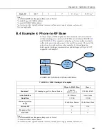
Страница 43: ...of the network The rest of the network can be configured as in other examples In this configuration datalogger to datalogger communications and datalogger call back is NOT supported see Example 5 Phone Modem Slave 2 Slave 1 PC Running LoggerNet PC400 Phone to RF451 Base FIGURE B 8 Schematic of Phone to RF Base TABLE B 4 RF451 Settings for Example 4 Phone to RF451 Base Slaves Hardware3 PC running L...

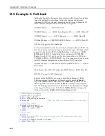
Страница 44: ...on is done by using an A100 Example configurations where call back is NOT supported LN Phone Modem COM220 CSI null modem RF451 Master RF451 Slave DL 1 LN Ethernet RavenXT rs232nullmodem RF451 Master RF451 Slave DL NOTE LN LoggerNet DL Datalogger In this example the RF451s are set up as described in Example 1 In the following program the datalogger will send a variable named Callback to LoggerNet P...

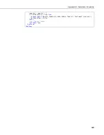
Страница 45: ...nstallation Scenarios B 9 counter counter 1 If CallbackFlag true Then SendVariables Result ComSDC7 0 4094 0000 0 Public Callback Scratch 1 CallbackFlag false EndIf Call Output Tables CallTable Test NextScan EndProg ...

Страница 46: ...Appendix B Installation Scenarios B 10 ...

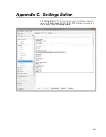
Страница 47: ...endix C Settings Editor The Settings Editor of DevConfig provides access to additional settings not shown on the Deployment tab Most RF451 RF450 networks do not need to make changes through the Settings Editor ...

Страница 48: ...e user to choose the portion of the band in which the transceiver will operate 0 Standard Full 902 928 MHz 1 Australia 915 928 MHz 2 International 903 744 926 3232 MHz 16 fewer frequencies than full U S set 3 Taiwan 916 920 MHz 4 New Zealand 921 928 MHz 5 Notch Uses 902 928 MHz with center frequencies of 911 919 MHz notched out 6 Brazil 902 915 MHz Do not use a Frequency Key Setting of 14 with a H...

Страница 49: ...mum link distance Greater antenna elevations not only provide greater obstacle clearance but also increase the maximum unobstructed line of sight distances over apparently flat terrain For example given 10 foot antenna elevations for both ends of a link and flat level terrain the maximum allowable distance between the antennas before the curvature of the earth begins to obstruct the RF line of sig...

Страница 50: ...ation of the RF signal as it propagates through the transmission lines coaxial cables surge suppressor etc connecting the transmitter and receiver to their respective antennas and more importantly as it traverses the path of propagation between the antennas path loss Here is a block diagram of the various components of gain loss Cable Loss Antenna Gain Path Loss Antenna Gain Cable Loss Radio Recei...

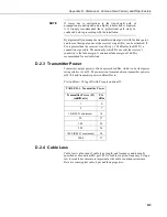
Страница 51: ...tivity is the fade margin A minimum fade margin of 10 dB is recommended for a reliable link D 2 3 Transmitter Power Transmitter output power is often expressed in dBm which is a decibel power rating relative to 1 mW The conversion formula between transmitter power in mW Pt and transmitter power in dBm Ptx is Ptx in dBm 10 log Pt with Pt expressed in mW TABLE D 1 Transmitter Power Transmitter Power...

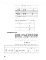
Страница 52: ... free space path loss and all other factors being equal an increase of 6dB in antenna gain theoretically extends the attainable distance by a factor of 2 An antenna s gain is a function of directivity For highly directive antennas such as the Yagi the narrower beam width makes antenna alignment and orientation more critical Antenna gain is specified either in dBi decibels of gain relative to an is...

Страница 53: ...nship between path loss and distance each time you double the distance you lose 6 dB of signal under free space conditions Or put another way if you add 6 dB of gain for example with 6 dB of additional antenna gain or 6 dB less cable loss you can double the distance for free space conditions As mentioned before free space conditions are the ideal but seldom actually seen The greater the antenna el...

Страница 54: ...0 ft respectively TABLE D 6 915 MHz Distance vs Path Loss Lpath in dB per Two Propagation Models Path Type 2 mi 4 mi 6 mi 8 mi 10 mi 14 mi 18 mi 22 mi 26 mi 30 mi Free Space 102 108 111 114 116 119 121 123 124 125 2 Ray 112 124 131 136 140 145 150 153 156 159 30 ft and 10 ft antenna elevations Often the maximum path distance may be constrained more by the antenna elevations than the path loss This...

Страница 55: ...nnas at 10 ft height fairly open terrain with a few trees How far can I go Ptx 30 dBm Ltx 20 ft 11 1 dB 100 ft 2 22 dB Gtx Grx 3 dBd 5 15 dBi Lrx 10 ft 11 1 dB 100 ft 1 11 dB From Appendix D 3 Real World Distance Estimates p D 5 we know Lpath 2 Ray 120 20log htx hrx 40Log d h in meters d in km Lpath 2 Ray 120 20log 3 05 3 05 40Log 1 609 d in mi Lpath 2 Ray 120 19 37 40Log 1 609 d in mi Lpath 2 Ray...

Страница 56: ...f LMR195 cable on a 4 ft pole Terrain is mostly flat with sagebrush How far can I go Pt 30 dBm Lt 50 ft 11 1 dB 100 ft 5 55 dB Gt 9 dBd 11 15 dBi Lr 5 ft 11 1 dB 100 ft 0 55 dB Gr 9 dBd 11 15 dBi Need to include an additional loss from the surge suppressor Lss 0 34 dB loss From Appendix D 3 Real World Distance Estimates p D 5 we know Lpath 2 Ray 120 20log htx hrx 40Log d h in meters d in km Lpath ...

Страница 57: ... LOSMAX for this link is approximately 10 5 miles so increasing antenna gain would not provide much of an increase in distance However increasing antenna elevation at one or both ends of the link could be beneficial Example 3 You need to run 125 ft of cable for the transmitter How much loss if I use LMR195 cable 125 ft 11 1 dB 100 ft 13 9 dB How much loss if I use LMR400 cable 125 ft 3 9 dB 100 ft...

Страница 58: ...Appendix D Distance vs Antenna Gain Terrain and Other Factors D 10 ...

Страница 59: ...1s will interfere with the RF401A RF401s and CR206 X s transmissions If RF451s and RF401A RF401 CR206 X s must be used in the same network there are some things you can do to obtain better performance out of the RF401A RF401 portion of your network 1 Use Yagi antennas and separate them 2 On the RF451 disable Frequency Zone 4 through Frequency Zone 11 set them to 0 or set the Hop Table Version to N...

Страница 60: ......

Страница 61: ......

Страница 62: ...Rua Apinagés nbr 2018 Perdizes CEP 01258 00 São Paulo SP BRASIL www campbellsci com br vendas campbellsci com br Campbell Scientific Canada Corp 14532 131 Avenue NW Edmonton AB T5L 4X4 CANADA www campbellsci ca dataloggers campbellsci ca Campbell Scientific Centro Caribe S A 300 N Cementerio Edificio Breller Santo Domingo Heredia 40305 COSTA RICA www campbellsci cc info campbellsci cc Campbell Sci...

Отзывы: