


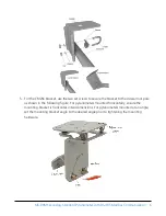


6. Verify mounting hardware is firmly tightened, and that the mounting bracket is at the
desired angle.
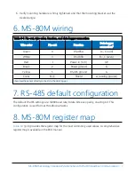
6. MS-80M wiring
Table 6-1: Pin-out, wire color, function, and data logger connection
Wire color
Pin-out
Function
Data logger
connection
1
Green
4
RS-485A
A–, C (odd)
White
3
RS-485B
B+, C (even)
Red
1
Power in (12 V)
12V
Black
2
Power ground
G
Yellow
5
RS-485 ground
G
Clear
N/C
Shield
⏚
(analog ground)
1
Assumes the sensor directly connects to the data logger.
7. RS-485 default configuration
The default RS-485 settings are: 19200 baud rate, 8 data bits, even parity, one stop bit. This
configuration is used for most Modbus networks.
8. MS-80M register map
(p. 8) provides the register map for the most commonly used values. A comprehensive
register map is available in the EKO manual.
MS-80M Secondary Standard Pyranometer with RS-485 Modbus Communication
7


