


Section 8. Operation
467
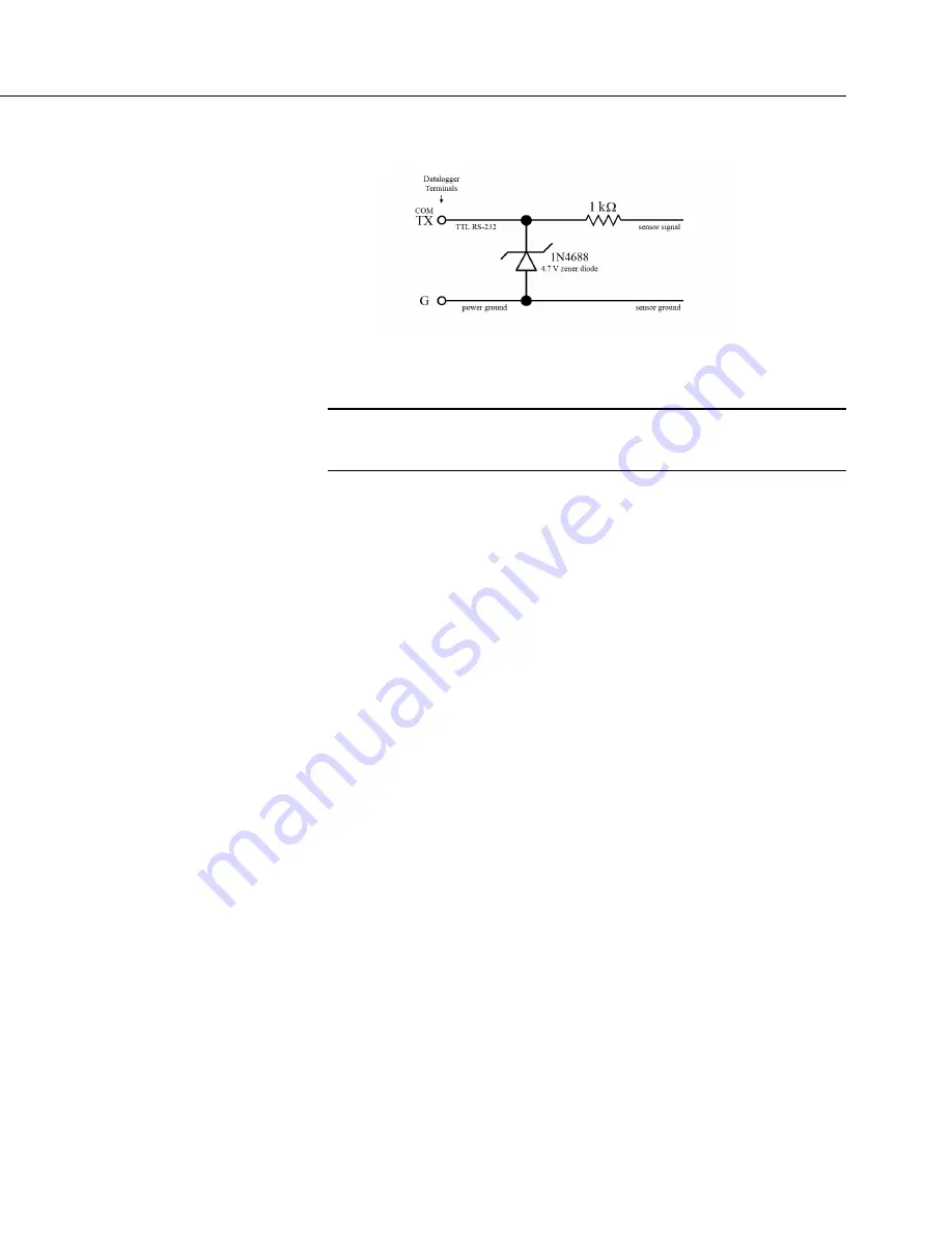
FIGURE 112: Circuit to Limit C Terminal Input to 5 Vdc
8.1.6.2 RS-485 — Overview
Related Topics:
•
RS-485 — Overview
•
RS-485 — Details
CR6
C
terminals can be configured for RS-485 communications. RS-485
communications are typically used for the following:
•
Reading sensors with RS-485 output
•
Creating a multi-drop network
•
Communication with other dataloggers or devices over long cable runs
Choose from three modes when configuring the CR6 for RS-485:
•
RS-485 Half-Duplex PakBus
The port is configured as RS-485 half-duplex (two wire) and optimized
for the PakBus protocol. This allows reliable PakBus networking of
multiple devices including the MD485 and NL100 using the RS-485
interface.
•
RS-485 Half-Duplex Transparent
The port is configured as RS-485 half-duplex (two wire). This setting is
most commonly used when communicating with other non-PakBus
RS-485 devices. Use this setting when communicating with devices such
as Modbus RTUs or third-party serial sensors with RS-485 interfaces.
•
RS-485 Full Duplex Transparent
The port is configured as RS-485 full-duplex (four wire). In this
configuration, four
C
terminals are required. This setting is most
commonly used when the transmitting and receiving of data is required
to happen at the same time.
Configure the comports with
Device Configuration Utility
as shown in the
following figure:
Содержание CR6 Series
Страница 2: ......
Страница 4: ......
Страница 6: ......
Страница 32: ......
Страница 36: ......
Страница 38: ......
Страница 76: ...Section 5 Overview 76 FIGURE 20 Half Bridge Wiring Example Wind Vane Potentiometer ...
Страница 80: ...Section 5 Overview 80 FIGURE 23 Pulse Input Wiring Example Anemometer ...
Страница 136: ......
Страница 251: ...Section 7 Installation 251 FIGURE 46 Running Average Frequency Response FIGURE 47 Running Average Signal Attenuation ...
Страница 454: ...Section 8 Operation 454 FIGURE 104 Narrow Sweep High Noise ...
Страница 459: ...Section 8 Operation 459 FIGURE 106 Vibrating Wire Sensor Calibration Report ...
Страница 535: ...Section 8 Operation 535 8 11 2 Data Display FIGURE 121 CR1000KD Displaying Data ...
Страница 537: ...Section 8 Operation 537 FIGURE 123 CR1000KD Real Time Custom ...
Страница 538: ...Section 8 Operation 538 8 11 2 3 Final Storage Data FIGURE 124 CR1000KD Final Storage Data ...
Страница 539: ...Section 8 Operation 539 8 11 3 Run Stop Program FIGURE 125 CR1000KD Run Stop Program ...
Страница 541: ...Section 8 Operation 541 FIGURE 127 CR1000KD File Edit ...
Страница 542: ...Section 8 Operation 542 8 11 5 PCCard Memory Card Management FIGURE 128 CR1000KD PCCard Memory Card Management ...
Страница 546: ......
Страница 549: ...Section 9 Maintenance Details 549 FIGURE 133 Separate Back Shell from Module FIGURE 134 Disconnect Battery Connector ...
Страница 552: ......
Страница 610: ...Section 11 Glossary 610 FIGURE 137 Relationships of Accuracy Precision and Resolution ...
Страница 612: ......
Страница 648: ......
Страница 650: ......
Страница 688: ......
Страница 689: ......