


Section 8. Operation
426
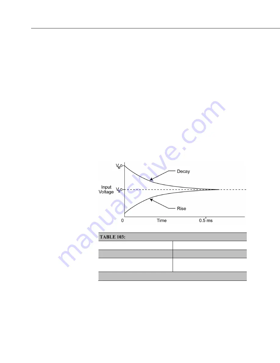
The rate at which the signal settles is determined by the input settling time
constant, which is a function of both the source resistance and fixed-input
capacitance (4.7 nfd) of the CR6.
Rise and decay waveforms are exponential. Figure
Input Voltage Rise and
Transient Decay
(p. 393)
shows rising and decaying waveforms settling closer to the
true signal magnitude, V
so
. The
SettlingTime
parameter of an analog
measurement instruction allows tailoring of measurement instruction settling
times with 100 µs resolution up to 600000 µs.
Settling times are listed in table
CRBasic Measurement Settling Times
(p. 393).
Default settling times (those resulting when
SettlingTime
=
0
) provide sufficient
settling in most cases. Additional settling time is often programmed when
measuring high-resistance (high-impedance) sensors or when sensors connect to
the input terminals by long leads.
Measurement time of a given instruction increases with increasing settling time.
For example, a 1 ms increase in settling time for a bridge instruction with input
reversal and excitation reversal results in a 4 ms increase in time for the CR6 to
perform the instruction.
FIGURE 91: Input voltage rise and transient decay
b
CRBasic Measurement Settling Times
SettlingTime
Argument
Resultant Settling Time
1
0
500 µs
integer between
100
and
600000
,
inclusive
μs entered in
SettlingTime
argument
1
500 µs is the default voltage measurement settling time.
Settling Errors
When sensors require long lead lengths, use the following general practices to
minimize settling errors:
•
Do not use wire with PVC-insulated conductors. PVC has a high
dielectric constant, which extends input settling time.
Содержание CR6 Series
Страница 2: ......
Страница 4: ......
Страница 6: ......
Страница 32: ......
Страница 36: ......
Страница 38: ......
Страница 76: ...Section 5 Overview 76 FIGURE 20 Half Bridge Wiring Example Wind Vane Potentiometer ...
Страница 80: ...Section 5 Overview 80 FIGURE 23 Pulse Input Wiring Example Anemometer ...
Страница 136: ......
Страница 251: ...Section 7 Installation 251 FIGURE 46 Running Average Frequency Response FIGURE 47 Running Average Signal Attenuation ...
Страница 454: ...Section 8 Operation 454 FIGURE 104 Narrow Sweep High Noise ...
Страница 459: ...Section 8 Operation 459 FIGURE 106 Vibrating Wire Sensor Calibration Report ...
Страница 535: ...Section 8 Operation 535 8 11 2 Data Display FIGURE 121 CR1000KD Displaying Data ...
Страница 537: ...Section 8 Operation 537 FIGURE 123 CR1000KD Real Time Custom ...
Страница 538: ...Section 8 Operation 538 8 11 2 3 Final Storage Data FIGURE 124 CR1000KD Final Storage Data ...
Страница 539: ...Section 8 Operation 539 8 11 3 Run Stop Program FIGURE 125 CR1000KD Run Stop Program ...
Страница 541: ...Section 8 Operation 541 FIGURE 127 CR1000KD File Edit ...
Страница 542: ...Section 8 Operation 542 8 11 5 PCCard Memory Card Management FIGURE 128 CR1000KD PCCard Memory Card Management ...
Страница 546: ......
Страница 549: ...Section 9 Maintenance Details 549 FIGURE 133 Separate Back Shell from Module FIGURE 134 Disconnect Battery Connector ...
Страница 552: ......
Страница 610: ...Section 11 Glossary 610 FIGURE 137 Relationships of Accuracy Precision and Resolution ...
Страница 612: ......
Страница 648: ......
Страница 650: ......
Страница 688: ......
Страница 689: ......


