


Section 7. Installation
177
Pros/Cons
This method is preferred because the user must manually configure the datalogger
to receive an OS and thus should be cognizant of what is happening (loss of data,
program being stopped, etc.).
Loading an operating system through this method will do the following:
1. Preserve all CR6 settings
2. Delete all data in final storage
3. Delete USR: drive
4. Stop current program deletes data and clears run options
5. Deletes data generated using the
CardOut()
or
TableFile()
instructions
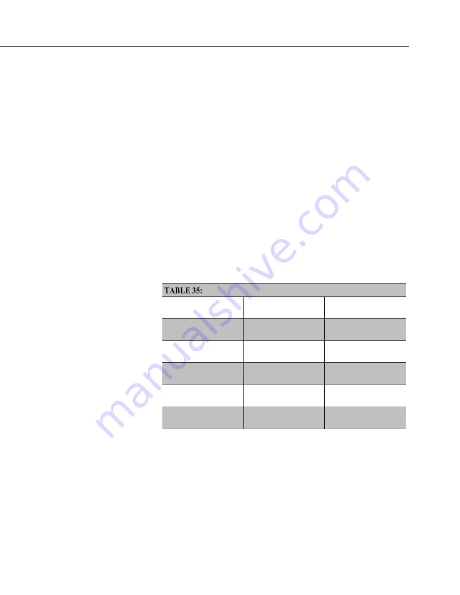
7.5.2.2.3 OS Update with Send Program Command
A send program command is a feature of
DevConfig
and other
datalogger support
software
Location of this command in the software is listed in the following
table:
Program Send Command Locations
Datalogger Support
Software
Name of Button
Location of Button
DevConfig
Send Program
Logger Control
tab
lower left
LoggerNet
Send New...
Connect
window, lower
right
PC400
Send Program
Main window, lower
right
PC200W
Send Program
Main window, lower
right
RTDAQ
Send Program
Main window, lower
right
This method results in the CR6 retaining its settings (a feature since OS version
16). The new OS file is temporarily stored in CR6 SRAM memory, which
necessitates the following:
•
Sufficient memory needs to be available. Before attempting to send the
OS, you may need to delete other files in the CPU: and USR: drives, and
you may need to remove the USR: drive altogether. Since OS 25, older 2
MB CR6s do not have sufficient memory to perform this operation.
Содержание CR6 Series
Страница 2: ......
Страница 4: ......
Страница 6: ......
Страница 32: ......
Страница 36: ......
Страница 38: ......
Страница 76: ...Section 5 Overview 76 FIGURE 20 Half Bridge Wiring Example Wind Vane Potentiometer ...
Страница 80: ...Section 5 Overview 80 FIGURE 23 Pulse Input Wiring Example Anemometer ...
Страница 136: ......
Страница 251: ...Section 7 Installation 251 FIGURE 46 Running Average Frequency Response FIGURE 47 Running Average Signal Attenuation ...
Страница 454: ...Section 8 Operation 454 FIGURE 104 Narrow Sweep High Noise ...
Страница 459: ...Section 8 Operation 459 FIGURE 106 Vibrating Wire Sensor Calibration Report ...
Страница 535: ...Section 8 Operation 535 8 11 2 Data Display FIGURE 121 CR1000KD Displaying Data ...
Страница 537: ...Section 8 Operation 537 FIGURE 123 CR1000KD Real Time Custom ...
Страница 538: ...Section 8 Operation 538 8 11 2 3 Final Storage Data FIGURE 124 CR1000KD Final Storage Data ...
Страница 539: ...Section 8 Operation 539 8 11 3 Run Stop Program FIGURE 125 CR1000KD Run Stop Program ...
Страница 541: ...Section 8 Operation 541 FIGURE 127 CR1000KD File Edit ...
Страница 542: ...Section 8 Operation 542 8 11 5 PCCard Memory Card Management FIGURE 128 CR1000KD PCCard Memory Card Management ...
Страница 546: ......
Страница 549: ...Section 9 Maintenance Details 549 FIGURE 133 Separate Back Shell from Module FIGURE 134 Disconnect Battery Connector ...
Страница 552: ......
Страница 610: ...Section 11 Glossary 610 FIGURE 137 Relationships of Accuracy Precision and Resolution ...
Страница 612: ......
Страница 648: ......
Страница 650: ......
Страница 688: ......
Страница 689: ......


