


Section 7. Installation
141
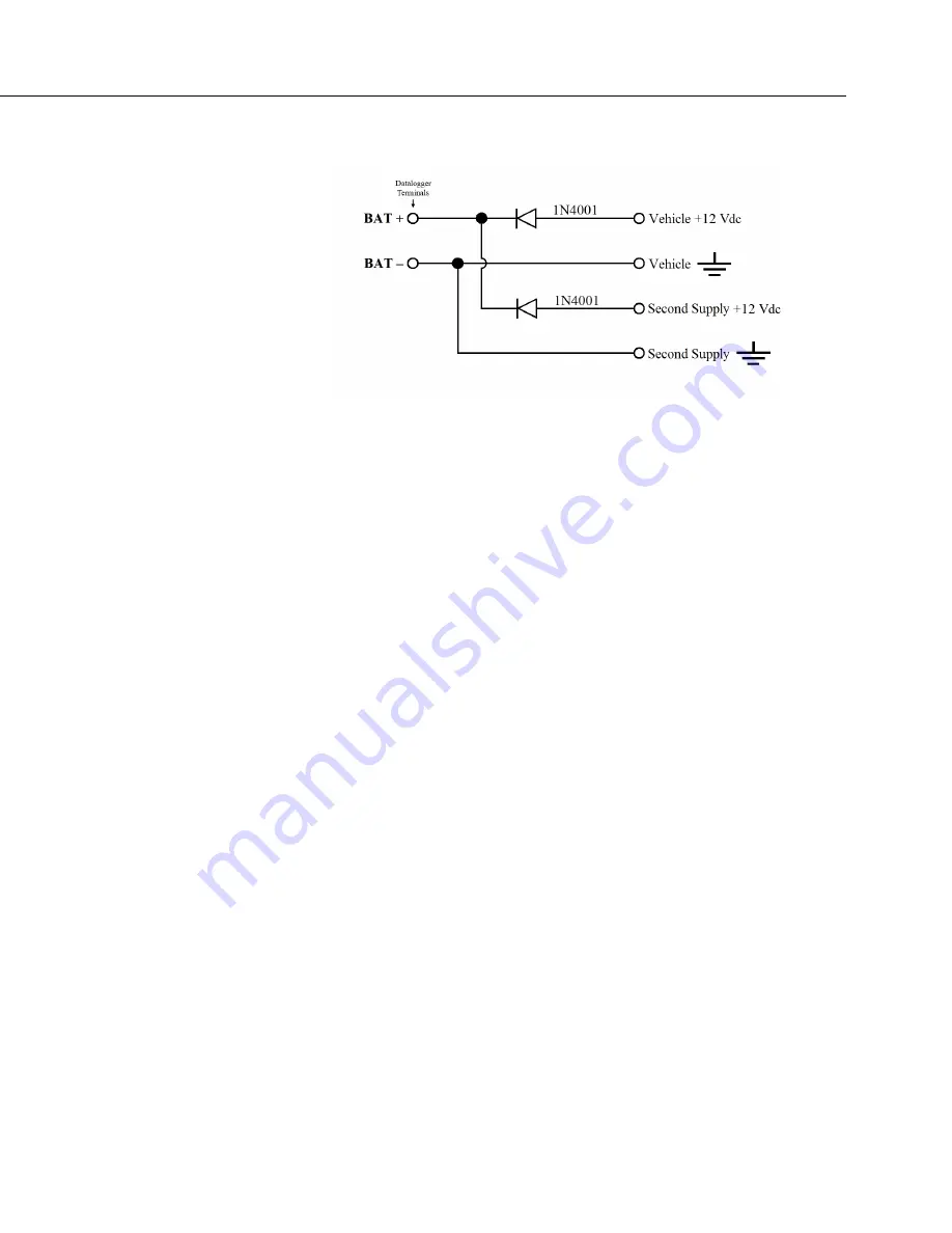
FIGURE 35: Connecting to Vehicle Power Supply
7.2.3 Uninterruptable Power Supply (UPS)
See
Power Input Terminals — Specifications
(p. 122)
for voltage and current limits.
A UPS (un-interruptible power supply) is often the best power source for
long-term installations. An external UPS consists of a primary-power source, the
charging regulator already integrated into the CR6, and an external battery. The
primary power source, which is often a transformer, power converter, or solar
panel, connects to the
CHG
terminals while a nominal 12 Vdc
sealed-rechargeable battery is connected to the
BAT
terminals.
Connect a rechargeable battery to the
BAT
terminals. The battery must be a
sealed rechargeable nominal 12 Vdc lead acid.
Connect a primary power source, such as a solar panel or Vac-to-Vdc transformer,
to
CHG
. The primary power source can be a 12 or 24 Vdc solar panel, or a Class
2, 24 Vdc power suppl. See
Primary Power Sources — List
(p. 668).
For sealed rechargeable lead acid batteries, the charge voltage requirement is 13.4
(slow) to 13.8 (fast) Vdc. The ideal charging voltage for batteries changes as
temperature changes, so provide an adequate buffer in the primary power source
in installations where significant temperature fluctuations are expected.
7.2.4 External Alkaline Power Supply
If external alkaline power is used, the alkaline battery pack is connected directly
to the
BAT
terminals. Voltage input range is 10 to 16 Vdc.
7.3
Grounding — Details
Grounding the CR6 with its peripheral devices and sensors is critical in all
applications. Proper grounding will ensure maximum ESD (electrostatic
discharge) protection and measurement accuracy.
Содержание CR6 Series
Страница 2: ......
Страница 4: ......
Страница 6: ......
Страница 32: ......
Страница 36: ......
Страница 38: ......
Страница 76: ...Section 5 Overview 76 FIGURE 20 Half Bridge Wiring Example Wind Vane Potentiometer ...
Страница 80: ...Section 5 Overview 80 FIGURE 23 Pulse Input Wiring Example Anemometer ...
Страница 136: ......
Страница 251: ...Section 7 Installation 251 FIGURE 46 Running Average Frequency Response FIGURE 47 Running Average Signal Attenuation ...
Страница 454: ...Section 8 Operation 454 FIGURE 104 Narrow Sweep High Noise ...
Страница 459: ...Section 8 Operation 459 FIGURE 106 Vibrating Wire Sensor Calibration Report ...
Страница 535: ...Section 8 Operation 535 8 11 2 Data Display FIGURE 121 CR1000KD Displaying Data ...
Страница 537: ...Section 8 Operation 537 FIGURE 123 CR1000KD Real Time Custom ...
Страница 538: ...Section 8 Operation 538 8 11 2 3 Final Storage Data FIGURE 124 CR1000KD Final Storage Data ...
Страница 539: ...Section 8 Operation 539 8 11 3 Run Stop Program FIGURE 125 CR1000KD Run Stop Program ...
Страница 541: ...Section 8 Operation 541 FIGURE 127 CR1000KD File Edit ...
Страница 542: ...Section 8 Operation 542 8 11 5 PCCard Memory Card Management FIGURE 128 CR1000KD PCCard Memory Card Management ...
Страница 546: ......
Страница 549: ...Section 9 Maintenance Details 549 FIGURE 133 Separate Back Shell from Module FIGURE 134 Disconnect Battery Connector ...
Страница 552: ......
Страница 610: ...Section 11 Glossary 610 FIGURE 137 Relationships of Accuracy Precision and Resolution ...
Страница 612: ......
Страница 648: ......
Страница 650: ......
Страница 688: ......
Страница 689: ......


