


101
6. Specifications
Campbell Scientific has calibrated and tested your CR6 datalogger and guarantees
it to meet the following electrical specifications in a –40 to 70 °C non-condensing
environment. A calibration sheet is provided with the original purchase. See
Warranty
(p. 3).
By special order, the temperature specification can be extended to
–55 to 85 °C. Before purchasing a CR6, please review the intended use and
critical specifications with a Campbell Scientific sales engineer.
6.1
Programmable Terminals — Specifications
You can program terminals
C1
–
C4
and
U1
–
U12
for analog, pulse, or digital
I/O functions. With certain restrictions, you can mix terminals programmed for
the analog function with terminals configured for the pulse count and digital I/O
functions.
Each odd numbered
U
and
C
terminal is paired with the even numbered terminal
next in the series, for example
U1
/
U2
and
C1
/
C2
. If one of a pair is configured
for a function (analog input, digital I/O, etc.) or logic level (3.3 or 5 V), the paired
terminal must be used in the same function and at the same logic level.
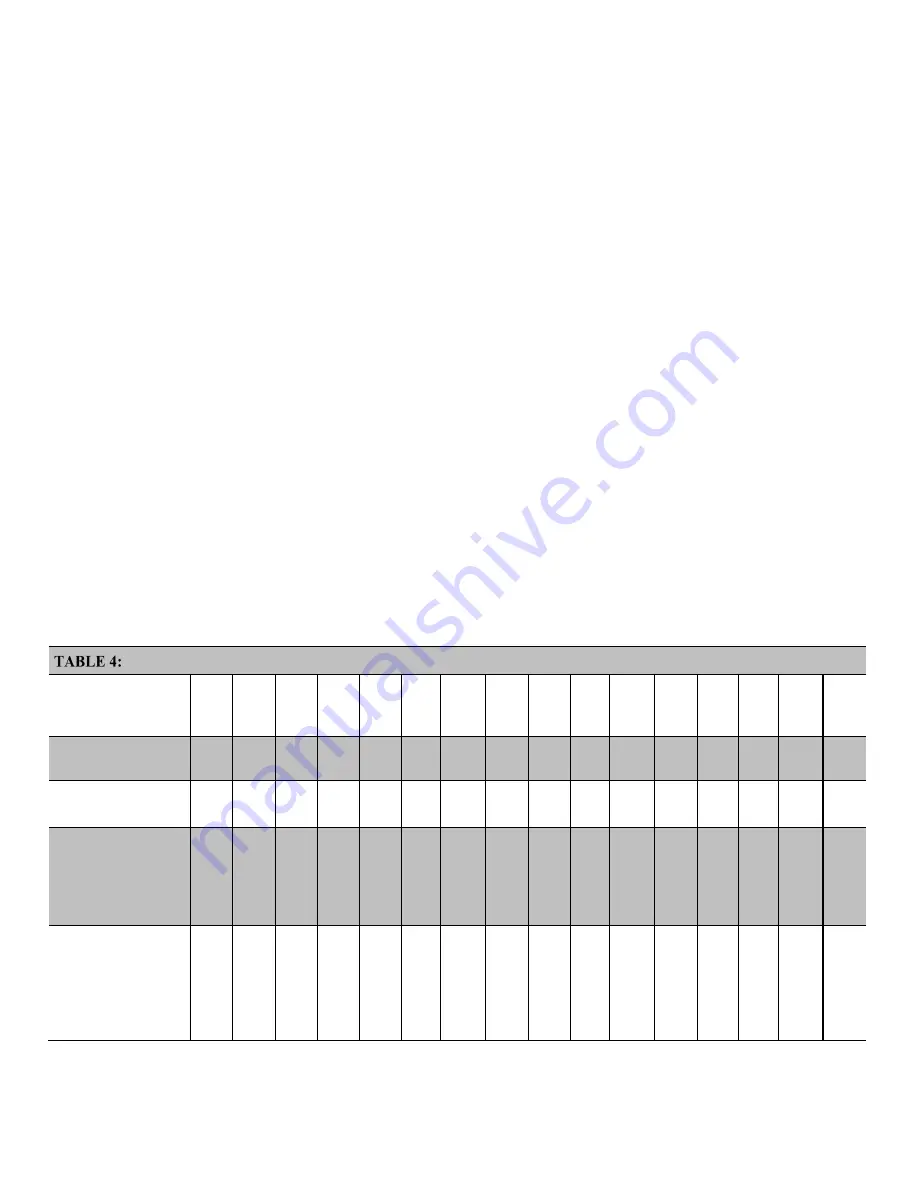
6.1.1 Analog Function: Input — Specifications
The following table shows terminals with analog-input functions:
Programmable Terminals — Analog Function: Input
Terminal Label
============
Function
C1
C2
C3
C4
U1
U2
U3
U4
U5
U6
U7
U8
U9
U10
U11
U12
Single ended
VoltSE()
Differential
1
VoltDiff()
H
L
H
L
H
L
H
L
H
L
H
L
Single ended
resistance
2
BRHalf()
BRHalf3W()
Resistance3W()
Differential
resistance
2
BRHalf4W()
BRFull()
BRFull6W()
Resistance()
H
L
H
L
H
L
H
L
H
L
H
L
Содержание CR6 Series
Страница 2: ......
Страница 4: ......
Страница 6: ......
Страница 32: ......
Страница 36: ......
Страница 38: ......
Страница 76: ...Section 5 Overview 76 FIGURE 20 Half Bridge Wiring Example Wind Vane Potentiometer ...
Страница 80: ...Section 5 Overview 80 FIGURE 23 Pulse Input Wiring Example Anemometer ...
Страница 136: ......
Страница 251: ...Section 7 Installation 251 FIGURE 46 Running Average Frequency Response FIGURE 47 Running Average Signal Attenuation ...
Страница 454: ...Section 8 Operation 454 FIGURE 104 Narrow Sweep High Noise ...
Страница 459: ...Section 8 Operation 459 FIGURE 106 Vibrating Wire Sensor Calibration Report ...
Страница 535: ...Section 8 Operation 535 8 11 2 Data Display FIGURE 121 CR1000KD Displaying Data ...
Страница 537: ...Section 8 Operation 537 FIGURE 123 CR1000KD Real Time Custom ...
Страница 538: ...Section 8 Operation 538 8 11 2 3 Final Storage Data FIGURE 124 CR1000KD Final Storage Data ...
Страница 539: ...Section 8 Operation 539 8 11 3 Run Stop Program FIGURE 125 CR1000KD Run Stop Program ...
Страница 541: ...Section 8 Operation 541 FIGURE 127 CR1000KD File Edit ...
Страница 542: ...Section 8 Operation 542 8 11 5 PCCard Memory Card Management FIGURE 128 CR1000KD PCCard Memory Card Management ...
Страница 546: ......
Страница 549: ...Section 9 Maintenance Details 549 FIGURE 133 Separate Back Shell from Module FIGURE 134 Disconnect Battery Connector ...
Страница 552: ......
Страница 610: ...Section 11 Glossary 610 FIGURE 137 Relationships of Accuracy Precision and Resolution ...
Страница 612: ......
Страница 648: ......
Страница 650: ......
Страница 688: ......
Страница 689: ......


