


CR10X User Guide
1-12
1.5.3 Allocation of Final Storage Area 2 when using the CR10X
with Extended Memory Options (Flash EEPROM)
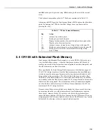
The default setting for a CR10X with extended flash memory is for all available
memory (i.e. the normal amount of RAM plus all the flash memory) to be
allocated to Final Storage Area 1 (FS1). If you choose to allocate some memory
for Final Storage Area 2 (FS2), note that:
•
The CR10X first uses RAM.
•
If the amount of memory you have allocated to FS2 exceeds that available
in RAM, the CR10X then allocates some of the flash memory as well.
•
If flash memory is required, the CR10X may have to adjust the size of FS2 to
force the division between Areas 1 and 2 to align with the nearest flash page.
Because writing to flash memory is slightly slower, you may want to use Area 2
for more frequently-stored data, ensuring that you do not allow the size of Area 2
to exceed the available RAM. For example, assigning 62,280 locations to Area 2
will segregate the memory between flash (Area 1) and RAM (Area 2).
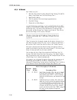
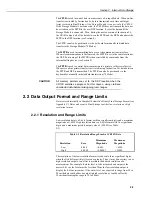
There are some limitations to the exact number of locations that can be entered
when reallocating memory between FS1 and FS2. For the 2MB version of the
CR10X the number of locations are as follows:
Final Storage Area 1
Final Storage Area 2
Minimum allocation:
131,072
114,689
Default allocation:
983,040
127,816
Maximum allocation:
983,040
980,890
For the 2MB version you will also have to allow for, and deduct, the memory
required for input, intermediate location and active program storage from the
maximum available space.
1.6 Memory Testing and System Status — *B Mode
The *B Mode is used to:
1.
Read the signature of the program memory.
2.
Display the operating system signature.
3.
Display the memory size (Flash and SRAM).
4.
Display the number of E08 occurrences (see Section 3 for a description of
error codes).
5.
Display the number of overrun occurrences.
6.
Display the operating system version number.
7.
Display the lithium battery voltage.
8.
Display the low 12V battery detect counter.
Table 1-5 describes what the values seen in the *B Mode represent.
A signature is a number which is a function of the data and the sequence of data in
memory. It is derived using an algorithm which ensures a 99.998% probability
that if either the data or its sequence changes, the signature changes. The signature
of the program memory is used to determine if the program tables have been
altered. During the self check on reset the signature computed for the operating
system is compared with a stored signature to determine if a failure has occurred.
The algorithm used to calculate the signature is described in Appendix C.