


LF-2
10-1 Determination of Quadrant for Instruction 66...................................... 10-23
13-1 50Hz Noise Rejection............................................................................. 13-1
13-2 Timing of Single-Ended Measurement .................................................. 13-2
13-3 Differential Voltage Measurement Sequence......................................... 13-2
13-4 Input Voltage Rise and Transient Decay................................................ 13-4
13-5 Typical Resistive Half Bridge ................................................................ 13-6
13-6 Source Resistance Model for Half Bridge Connected to the CR10X..... 13-6
13-7 Wire Manufacturers’ Capacitance Specifications, C
w
............................. 13-7
13-8 Model 024A Wind Direction Sensor...................................................... 13-7
13-9 Resistive Half Bridge Connected to Single-Ended CR10X Input .......... 13-9
13-10 Half Bridge Configuration for YSI #44032 Thermistor Connected
to CR10X............................................................................................ 13-12
13-11 Measuring Input Settling Error with the CR10X................................ 13-13
13-12 Incorrect Lead Wire Extension on Model 107 Temperature
Sensor ................................................................................................. 13-13
13-13 Thermistor Polynomial Error ............................................................. 13-15
13-14 Diagram of Junction Box ................................................................... 13-19
13-15 Circuits Used with Instructions 4 to 9 ................................................ 13-20
13-16 Excitation and Measurement Sequence for 4-Wire Full Bridge......... 13-21
13-17 AC Excitation and Measurement Sequence for AC Half Bridge ....... 13-23
13-18 Model Of Resistive Sensor with Ground Loop .................................. 13-23
14-1 Connecting to Vehicle Power Supply..................................................... 14-3
14-2 CR10WP Wiring Panel Grounding Diagram and Excitation Control .... 14-4
14-3 Relay Driver Circuit with Relay............................................................. 14-6
14-4 Power Switching without Relay ............................................................. 14-6
14-5 Removing the Wiring Panel ................................................................... 14-8
14-6 Removing the End Cap .......................................................................... 14-9
14-7 Removing the Circuit Board from the Casing ........................................ 14-9
14-8 CR10X Lithium Battery Location .......................................................... 14-9
B-1 Circuit to Limit Input to 0 to 5V............................................................... B-7
B-2 Wiring Diagram for CR10X to CR10X Communication Example …. ..B-14
G-1 Example Station File Settings for 115.STN ............................................. G-4
G-2 Example .SCR File for Datalogger Initiated Communications ................ G-4
G-3 Computer Screen in PC208E/Telcom Waiting for a Call......................... G-5
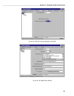
G-4 Example of Connect Settings ................................................................... G-6
G-5 COM Port Hardware Settings in PC208W ............................................... G-7
G-6 Example Modem Settings......................................................................... G-7
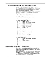
G-7 Data Collection Settings Example in PC208W ........................................ G-8
G-7 Example Schedule Settings in PC208W................................................... G-8