


CR10X Reference Manual
I-2
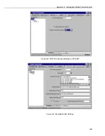
In the PC based software’s Modbus driver or with a PLC the communications
port, baud rate, data bits, stop bits, and parity are set. CR10/10Xs communicate at
9600, 1200, or 300 baud (they automatically connect at the baud rate of the
computer if its baud rate is lower than 9600), N,8,1.
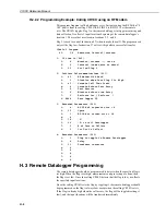
The Modbus address can be set in *D mode allowing multiple dataloggers on the
same serial port direct communications when using appropriate communications
hardware. The address is set in *D window 8. Valid addresses are 1 to 254 with
the exception of 13.
This can be done from the CR10KD or a computer terminal with a terminal
emulator. See section OV3 and section 5 of the CR10X manual for details.
I.2.1 RF Communications
The Campbell Scientific UHF/VHF radio package is, of course, compatible with
PC208W/PC208. To also use Modbus on SCADA packages using the Campbell
Scientific radio package, a special operation system PROM for the RF95 radio
modem is needed. The RF95 PROMs will facilitate an auto route to the correct
RF95. In this case, the RF95 address (dip switch) is set to the Modbus address of
the CR10/10X at each specific site. In the SCADA software, the COM port
settings and the Modbus address need to be set. No dialling is necessary as the
RF95s would connect through to the correct CR10/10X. Repeater stations are not
supported. All remote dataloggers must communicate directly with the RF232
base station.
Many popular radio systems for Modbus applications will not be compatible with
PC208W/PC208 if there is more than one remote site.
I.2.2 CR10/10X to CR10/10X Communication
Library special software is available that allows one CR10X to communicate with
another CR10X using Modbus in a P97 instruction. The standard implementation
of Modbus enables the CR10/10X to respond to Modbus commands, not to issue
them.
I.3 More about Modbus
Following is a brief explanation of the Modbus functions supported and the
strings that are transmitted. Most users will not need this information as the
CR10/10X and PC-based Modbus drivers handle this level of communication
transparent to the user. If more information is needed, please refer to Modicon’s
publication ‘Modicon Modbus Protocol Reference Guide’ (PI-MBUS-300
Rev. D), or contact Modicon directly.
Functions
supported
by CR10
Description
1
read coil status
3
read holding registers
5
force single coil
15
force multiple coils
16
preset multiple registers