


Section 13. CR10X Measurements
13-19
necessary to use extension grade wire instead of an external measuring junction is
where the junction box temperature is outside the range of reference junction
compensation provided by the CR10X. This is only a factor when using type K
thermocouples, where the upper limit of the reference compensation linearisation
is 100
o
C and the upper limit of the extension grade wire is 200
o
C. With the other
types of thermocouples, the reference compensation range is to equal to or greater
than the extension wire range. In any case, errors can arise if temperature
gradients exist within the junction box.
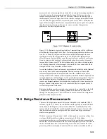
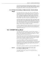
Figure 13-14 Diagram of Junction Box
Figure 13-14 illustrates a typical junction box. Terminal strips will be a different
metal than the thermocouple wire. Thus, if a temperature gradient exists between
A and A' or B and B', the junction box acts as another thermocouple in series,
creating an error in the voltage measured by the CR10X. This thermoelectric
offset voltage is a factor whether or not the junction box is used for the reference.
It can be minimised by making the thermal conduction between the two points
large and the distance small. The best solution in the case where extension grade
wire is being connected to thermocouple wire would be to use connectors which
clamped the two wires in contact with each other.
An external reference junction box must be constructed so that the entire terminal
area is very close to the same temperature. This is necessary so that a valid
reference temperature can be measured, and to avoid a thermoelectric offset
voltage which will be induced if the terminals at which the thermocouple leads are
connected (points A and B in Figure 13-14) are at different temperatures. The box
should contain elements of high thermal conductivity, which will act to rapidly
remove any thermal gradients to which the box is subjected. It is not necessary to
design a constant temperature box; it is desirable that the box respond slowly to
external temperature fluctuations.
Radiation shielding must be provided when a junction box is installed in the field.
Care must also be taken that a thermal gradient is not induced by conduction
through the incoming wires. The CR10X can be used to measure the temperature
gradients within the junction box.
13.5 Bridge Resistance Measurements
There are six bridge measurement instructions included in the standard CR10X
software. Figure 13-15 shows the circuits that would typically be used with these
instructions. In the diagrams, the resistors labelled R
s
would normally be the
sensors and those labelled R
f
would normally be fixed resistors. Circuits other
than those shown could be used, provided the excitation and type of measure-
ments were appropriate.
With the exception of Instructions 4 and 8, which apply an excitation voltage then
wait a specified time before making a measurement, all of the bridge
measurements make one set of measurements with the excitation as programmed
and another set of measurements with the excitation polarity reversed. The error in
the two measurements due to thermal voltages can then be accounted for in the
processing of the measurement instruction. The excitation is switched on 450µs