


CR10X Reference Manual
9-12
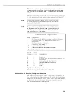
PARAM.
DATA
NUMBER
TYPE
DESCRIPTION
01:
2
Repetitions
02:
2
Range code (Tables 9-1 and 9-5)
03:
2
First TC channel (when indexed (--), becomes an input
location containing voltage measurement)
04:
2
Thermocouple type code (Table 9-4)
05:
4
Reference temperature location
06:
4
Destination input location
07:
FP
Multiplier
08:
FP
Offset
Input locations altered: 1 per repetition
Instruction 14: Thermocouple Temperature, Differential
Measurement
This instruction calculates the thermocouple temperature for the thermocouple
type selected. The instruction makes a differential voltage measurement on the
thermocouple, adds the measured voltage to the voltage calculated for the refer-
ence temperature relative to 0
o
C, and converts the combined voltage to
temperature in
o
C. The differential inputs are briefly shorted to ground before
making the voltage measurement to ensure that they are within the common mode
range. Table 9-4 gives the thermocouple type codes for parameter 4. Entering a 9
in front of the type code causes the CR10X to make an additional check on
common mode range; -99999 is output for temperature if the common mode range
is exceeded.
If you want to apply the Campbell Scientific polynomials to a millivolt value in
an input location without using the measurement part of Instruction 14, you
should index parameter 3 (the input channel number). The input location where
the thermocouple output (mV) is located is now defined by parameter 3. The
thermocouple must be measured with Instruction 2.
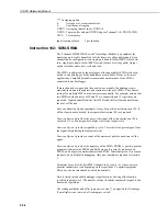
PARAM.
DATA
NUMBER
TYPE
DESCRIPTION
01:
2
Repetitions
02:
2
Range code (Tables 9-1 and 9-5)
03:
2
Differential Channel number for first TC (when indexed
(--), becomes an input location containing voltage
measurement)
04:
2
Thermocouple type code (Table 9-4)
05:
4
Reference temperature location
06:
4
Destination input location
07:
FP
Multiplier
08:
FP
Offset
Input locations altered: 1 per repetition
Instruction 15: Control Port Serial I/O
This instruction sends and receives serial data through the CR10X control ports.
See Appendix B for details on using Instruction 15.