


CR10X User Guide
7-2
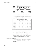
7-1. A short jumper wire is connected between Control Port 1 and the Switched
12V Control.
The Switched 12V Control terminal will be permanently
damaged if 12V is applied to it.
Never
connect 12V to this
terminal.
3H
3L
SWITCHED 12V
AG
G
C1
SWITCHED
12V
CONTROL
CR10X
Jumper
CS500
Temperature (Black)
Relative Humidity (Brown)
12 V (Red)
Signal/Power Ground (Green)
Shield (Clear)
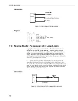
Figure 7-1 Wiring Diagram for 50Y
Program
;Turn 50Y on.
;
01:
Do(P86)
1:41
Set Port 1 High
;Allow the 50Y to warm up and stabilize on
;the Temperature and Relative Humidity.
;
02:
Excitation with Delay (P22)
1: 3
Ex Channel
2: 0
Delay W/Ex (units = 0.01 sec)
3:10
Delay After Ex (units = 0.01 sec)
4: 0
mV Excitation
;Measure Temperature.
;
03:
Volts (SE) (P1)
1: 1
Reps
2:35
±±±±
2500mV 50 Hz Rejection Range
3: 5
SE Channel
4: 1
Loc [ Temp_C ]
5:
.1
Mult
6:-40
Offset
;Measure Relative Humidity.
;
04:Volts (SE) (P1)
1: 1
Reps
2:35
±±±±
2500mV 50 Hz Rejection Range
3: 6
SE Channel
4: 2
Loc [ RH_pct ]
5:
.1
Mult
6: 0
Offset
CAUTION
(Yellow)
50Y
(Green)
(Blue)
(Braid)