Chapter 5: Installation
269
6
When you have achieved the best signal (highest pitch, loudest volume), lock the BHS in place with
the mounting hardware
Conf ig ur ing t he Link
See Configuring remote access in Configuration Guide.
Monit or ing t he Link
See Monitoring the Link in Configuration Guide.
Inst alling t he A C Po w er Inject o r
Caution
As the PSU is not waterproof, locate it away from sources of moisture, either in
the equipment building or in a ventilated moisture-proof enclosure. Do not locate
the PSU in a position where it may exceed its temperature rating.
Caution
Do not plug any device other than a PMP/PTP 450i Series ODU into the ODU port
of the PSU. Other devices may be damaged due to the non-standard techniques
employed to inject DC power into the Ethernet connection between the PSU and
the ODU.
Do not plug any device other than a Cambium 450 Platform PSU into the PSU
port of the ODU. Plugging any other device into the PSU port of the ODU may
damage the ODU and device.
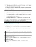
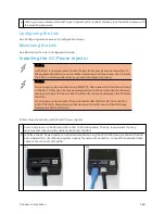
Follow this procedure to install the AC Power Injector:
1
Form a drip loop on the PSU end of the LPU to PSU drop cable. The drip loop ensures that any
moisture that runs down the cable cannot enter the PSU.
2
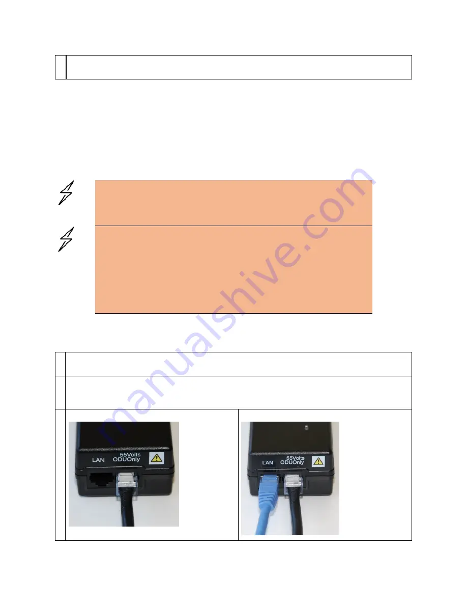
(a) Place the AC Power Injector on a horizontal surface. Plug the LPU to PSU drop cable into the PSU
port labeled ODU. (b) When the system is ready for network connection, connect the network Cat5e
cable to the LAN port of the PSU:
(a)
(b)
Содержание PMP 450 Series
Страница 92: ...Chapter 2 System hardware 92 Figure 29 MicroPoP Omni antenna implementation pattern Vertical...
Страница 134: ...Chapter 3 System planning 134 Figure 51 Mast or tower installation...
Страница 135: ...Chapter 3 System planning 135 Figure 52 Wall installation...
Страница 136: ...Chapter 3 System planning 136 Figure 53 Roof installation...
Страница 137: ...Chapter 3 System planning 137 Figure 54 GPS receiver wall installation...
Страница 158: ...Chapter 3 System planning 158 Figure 61 cnMedusa Antenna...
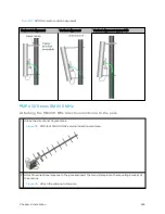
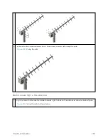
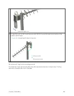
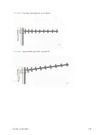
Страница 258: ...Chapter 5 Installation 258 Figure 123 Yagi antenna alignment horizontally Figure 124 Yagi antenna alignment upward tilt...

