CalreC
Putting Sound in the Picture
Modular Hydra I/O boxes allow a
user-configurable set of analog and
digital I/O to be connected via the
networking system to one or more
Calrec digital consoles.
Modular Structure
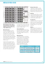
There are 14 modular slots across the
width of the unit, labelled A to N. Input,
output, processor and DC PSU modules
fit into these slots, in accordance with the
requirements of the installation. Input
and output modules receive and transmit
analog or digital audio signals, to the Gigabit
interface processor via a 32 bit TDM bus.
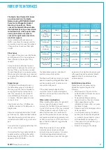
The module options are listed in the table
below. Each modular unit is 1.2 inches
(30.48 mm) wide.
All 14 slots may be used by any of the
modules in any combination. However, it
is advised that the three slots at the right
hand side of the unit are best occupied by
a processor control unit and provision for
two DC PSU modules, the second of which
would be the optional hot-spare, providing
power redundancy if the first unit, or the
connection to it should develop a fault.
mOdular Hydra I/O bOx
If no spare DC PSU is present, a blank panel
can be fitted or the processor unit can move
to slot M allowing a twelfth input or output
module to be fitted into slot L.
Ground Lift Switches
On modules with ground switches fitted,
the ground is lifted if the switch is toggled
to the right. Lifting ground connections
with unbalanced BNC connectors is not
reccomended.
Module Extraction
A module extraction hole is located on the
module front panels to help remove modules
for service purposes. The module slides in
and out the unit on two runners at the top
and bottom of the rack. The rear interface
connector on the module then locates into
the appropriate connector on the backplane.
To aid accurate plugging-up, some guide
strips are located between the three
interface connectors on the backplane.
External Connections
All external connections are located
on the front face of the Hydra I/O box.
Space must be allowed in excess of the
box dimensions to feed cables to the front
interface from any rear access routes.
Mounting
The modular Hydra I/O box is mounted
in place using 4 fixing screws on each
side angle bracket. Support slides should
normally be used to prevent excessive
twisting forces on the front fixings.
Fan Operation
To dissipate the heat, 3 low-noise fans are
located in the rear of the modular Hydra
I/O box. They are controlled from the DC
power supply unit. The unit’s rear panel
has venting holes which must not be
obstructed.
Earthing
The box is fitted with an external earth
stud on the rear, for connection to an
external earthing system. No AC mains
power is contained within the rack. All
power connections should be unplugged
prior to removing the earth connection.
Module
Number
Description
Connector
Type
AD5090
4 stereo or 8 mono mic/line inputs
XLR
LN5230
8 split outputs for adjacent left
mic/line input module
XLR
JB5340
4 AES inputs and 4 AES outputs
BNC
JX5341
4 AES inputs and 4 AES outputs
XLR
DA5091
4 stereo or 8 mono outputs
XLR
UC5339
Processor with copper interface
RJ45
ZN5231
DC Power Supply
8 PIN PLUG
Содержание OMEGA
Страница 7: ...calrec com OMEGA Putting Sound in the Picture Overview...
Страница 13: ...calrec com OMEGA Putting Sound in the Picture Frame Options and Dimensions...
Страница 18: ...18 OMEGA with Bluefin...
Страница 19: ...calrec com OMEGA Putting Sound in the Picture Equipment Installation...
Страница 37: ...calrec com OMEGA Putting Sound in the Picture Hydra Audio Networking...
Страница 51: ...calrec com OMEGA Putting Sound in the Picture Audio I O Interfaces...
Страница 69: ...CALREC Putting Sound in the Picture 69...

