background image

118   BRIO 36 

Audio Production System with Optional Networking

PROCESSING

PAN CONTROLS

The pan processing tab provides individual pan controls for each channel or group.  Separate pan controls are 
available for panning to mains and groups and to auxes and you can switch between them using the drop-down 
menu in the screen header.

Surround Mains and Groups

Surround panning controls are available when feeding mains and groups.  There are several ways to manipulate these 
controls:

Pan controls are accessed from the touch display.

• 

With the touch display in ‘active Show’ view, tap the Pan processing tab to access the relevant controls.                
Note: the appropriate context sensitive controls under the touchscreen illuminate to provide physical controls 

• 

From the surface, push the 

ACCESS 

control mode button to select which path the controls will act upon.   

• 

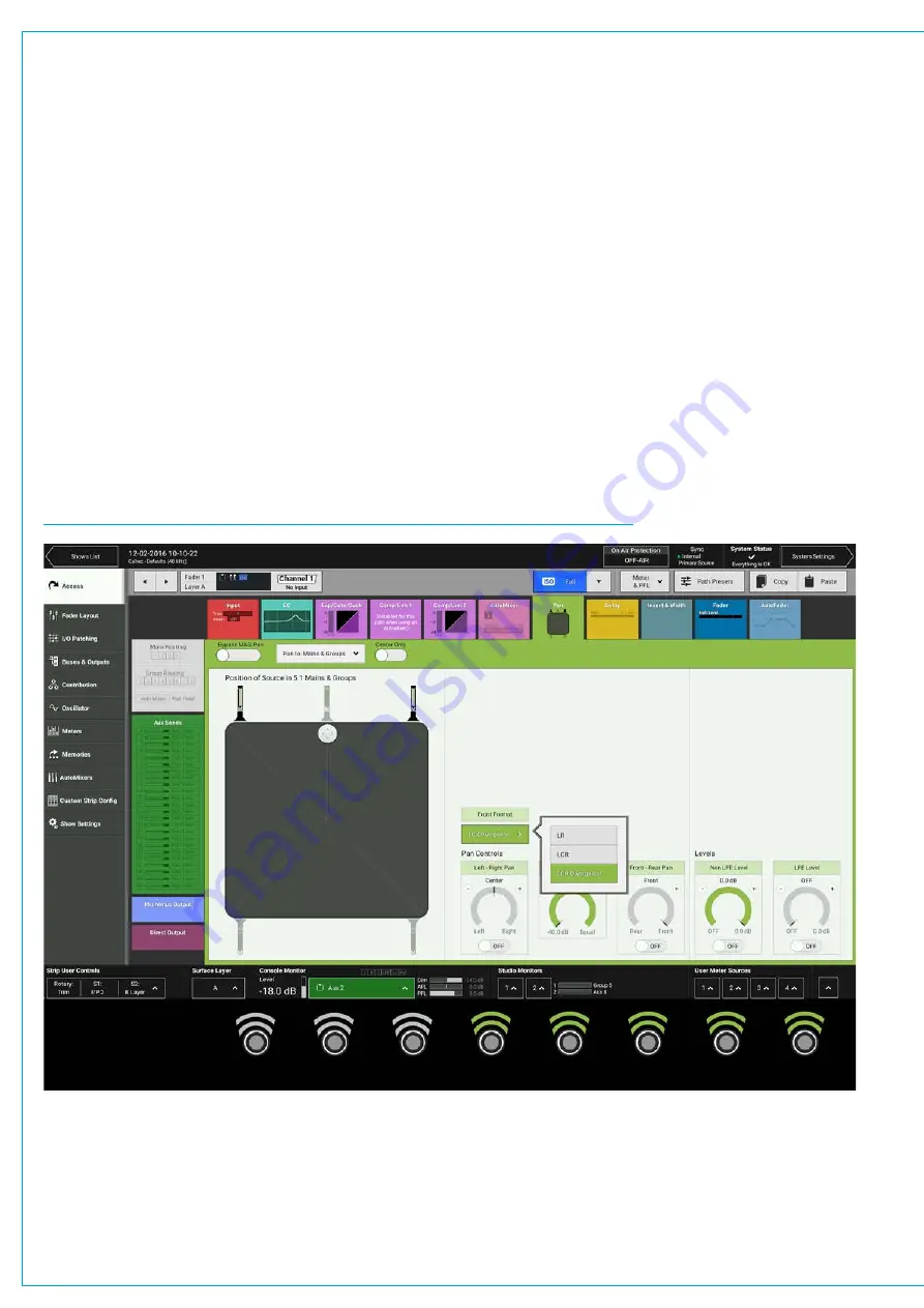
On the touch display there is a visual representation of the surround space to the left hand side of the 
panning screen. Tap a new location or drag the white disk to place the audio within the space.  Alternatively, 
there  are  rotary  controls  on  the  right  of  the  panning  screen  available  for  left/right  and  front/back  panning.                                                       
The pan context based controls and page are shown in Figure 1.

FIGURE 1 - 

CONTEXT CONTROLS—ACCESS MODE—MAINS & GROUPS PANNING

Содержание BRIO 36

Страница 1: ...calrec com Audio Production System with Optional Networking BRIO 36 USER MANUAL V1 1...

Страница 2: ...ernational usage Calrec Audio Ltd reserve the right to change specifications without notice E O E The established policy of Calrec Audio Ltd is to seek improvements to the design specifications and ma...

Страница 3: ...gistered 16 HEALTH AND SAFETY 17 Important Safety Instructions 17 Cleaning 17 Explanation of Warning Symbols 17 Earthing 18 Lithium Battery Replacement 18 PACKAGE CONTENTS 19 SYSTEM OVERVIEW 21 SURFAC...

Страница 4: ...ching 37 Hydra2 Patchbays at different sample rates 37 INTERFACING STYLES 38 Physical Controls 38 Touch Display 38 LAYERS 40 Layer Switching Options 40 Surface Layer Pop up 41 96KHZ OVERVIEW FOR BRIO...

Страница 5: ...58 Restoring Shows 59 Settings Stored within Shows 59 MEMORIES 60 Loading a User Memory 60 Creating a new User Memory 60 Updating a User Memory 60 Creating Multiple User Memories 61 Storage Capacity...

Страница 6: ...INPUT CONTROLS 79 I O Box Input Port 79 The Channel Input 79 Mic Gain 80 Providing Console Wide Strip User Controls 81 Group Input Controls 82 Linking Input 1 and Input 2 Trims 82 Replay 83 Stereo 5...

Страница 7: ...n independent Controls for Stereo and 5 1 Paths 105 Removing Independence from Spill Legs 105 DYNAMICS 106 Compressor Limiter 1 2 106 Expander Gate Ducker 108 Global Module Controls 108 Dynamics Links...

Страница 8: ...ing VCA Groups 127 VCA Group Status Indication 127 Secondary Master 128 Masters and Paths 129 Other VCA information 129 5 1 Surround Paths 130 VCA Group Protection 130 VCA Non Moving Faders 130 THE FA...

Страница 9: ...151 Monitoring External Inputs 151 Settings 151 PFL AFL AND OUTPUT LISTEN 153 AFL 153 PFL 153 Output Listen OPL 153 PFL Position in Audio Chain 153 Access from Faders 154 Access from the Touch Displa...

Страница 10: ...ut from its foldback mix 167 Mix Minus Output 167 Mix Minus using the Auto Minus bus 168 Mix Minus using Auxes 169 Setting up a Mix Minus output 169 Mix Minus Controls 169 Off Air Conference Bus 171 S...

Страница 11: ...MIC OPEN SYSTEMS AND ON AIR PROTECTION CONFIGURATION 188 Assigning Inputs to Mic Open Systems 189 Assigning to CUT DIM Loud Speakers for On Air Protection 189 Mic Open systems and multi leg paths 189...

Страница 12: ...12 BRIO 36 Audio Production System with Optional Networking...

Страница 13: ...calrec com BRIO 36 PRODUCT INFORMATION...

Страница 14: ...e on request Repairs If you need to return goods to Calrec for whatever reason please contact your regional distributor or Calrec customer support beforehand for guidance as well as to log the details...

Страница 15: ...quipment Calrec Audio Limited can not be liable for any legal proceedings or problems that may arise relating to such modifications If in doubt please contact Calrec Audio Limited for guidance prior t...

Страница 16: ...solder In the unlikely event of a customer having to carry out any re soldering on Apollo Artemis Summa Brio 36 or Hydra2 hardware it is imperative that lead free solder is used contaminating lead fr...

Страница 17: ...the risk of fire or electric shock do not expose this apparatus to rain or moisture Not intended for outdoor use This equipment must be EARTHED Before starting any servicing operation equipment must b...

Страница 18: ...This device may not cause harmful interference 2 This device must accept any interference received including interference that may cause undesired operation Other Symbols in Use For apparatus intende...

Страница 19: ...re Power Router Control Processor and DSP are all self contained within the unit which has 2 x IEC connectors to provide PSU redundancy The core operates at 44 1 48 88 2 96 kHz and supports 64 legs as...

Страница 20: ...20 BRIO 36 Audio Production System with Optional Networking...

Страница 21: ...calrec com BRIO 36 SYSTEM OVERVIEW...

Страница 22: ...as a Cut or and ON button The top right hand area contains the touchscreen UI area complete with touchscreen TFT 8 context based rotary controls 12 Global user switches G1 to G12 A B layer selection L...

Страница 23: ...12 fader section is made up of 12 fader strips each containing a motorised fader several push buttons a rotary control knob with built in switch and a small TFT fader display The image below explains...

Страница 24: ...been isolated from changes made by memory loads The ISO icon will be green if the path is partially isolated The VCA group status indicators show whether a fader or path is a Master SubMaster or Slav...

Страница 25: ...ary control is defined as the control cell situated at the top of each fader strip The function of these control cells varies depending on which control mode you have selected In normal mode all contr...

Страница 26: ...bove it Console Monitors The large rotary control bottom centre adjusts the console main monitor level the level indication is shown at the bottom of the touchscreen To the left of the monitor level c...

Страница 27: ...ace Layers The Brio surface has two layers allowing fader control of twice as many paths as there are faders on the surface i e 72 fader paths You can switch between layers using the Fader Layer selec...

Страница 28: ...he Active Show view is the main page and provides access to operation screens and settings for the currently loaded Show The Shows List button on the top left in the header provides access to the list...

Страница 29: ...29 FIGURE 1 BRIO 36 USER INTERFACE DISPLAY...

Страница 30: ...are colour coded as follows Channels black background white label Groups blue background white label Mains red background white label and Auxes green background white label Inputs Input Channels Inpu...

Страница 31: ...en patched to the talkback input in order to be used Buses Groups Multiple channel Inputs can be sub mixed by routing them to groups Groups can be processed Groups can be routed to any other output or...

Страница 32: ...able for patching and can have Equaliser Dynamics and Delay processing applied Path Outputs Mix Minus Outputs Each channel can have one mix minus output assigned to it from a pool of 64 mono legs shar...

Страница 33: ...roviding a send out and a return back in allowing devices like external effects processors to be placed within the signal flow of a path Insert sends and returns appear in the I O patching screen from...

Страница 34: ...34 BRIO 36 Audio Production System with Optional Networking SYSTEM OVERVIEW FIGURE 4 BRIO 36 AUDIO SCHEMATIC...

Страница 35: ...corresponding Hydra2 patchbay output Console Specific or Shared There are two types of HPB console specific and shared Console specific HPBs are available to H2O 3rd party controllers via SW P 08 as...

Страница 36: ...Hydra2 patchbay input either through a memory load or through changing the individual patch In these circumstances it is important that you understand the contents of the source and destination prote...

Страница 37: ...at point 1 FIGURE 3 HYDRA PATCHBAY UN PATCH Hydra2 Patchbays at different sample rates Note now different sample rates are available Hydra2 patchbays can be created to operate at a different sample ra...

Страница 38: ...no stopping point at either extreme This allows the surface to be fully flexible as all physical controls are able to control a wide range of functions within one project When a rotary control is atta...

Страница 39: ...le selection can be made by dragging the selection handles once an initial selection has been made as shown in Figure 1 FIGURE 1 DRAG HANDLES TO SELECT MULTIPLE ITEMS Buttons Switches Keyboard There a...

Страница 40: ...s button states and control cell states change immediately to reflect faders on the newly selected layer Paths are active and can pass audio on both layers regardless of whether they are currently in...

Страница 41: ...surface section is represented along the top of the pop up Link layer switches along the bottom of the pop up can be set to on or off to enable or disable layer linking Linked layers will always be on...

Страница 42: ...S3 Wordclock inputs even if all consoles and I O are at 96kHz The console patching screens and required list indicate which ports HPB aliases or boxes are at a different sample rate to the desk These...

Страница 43: ...calrec com BRIO 36 SETTING UP...

Страница 44: ...on the meter displays PPM or VU scales can be chosen along with various colour split points controlling the level ranges of the green yellow and red elements of the meter bar graphs Cut On button func...

Страница 45: ...all displays and Touchscreen display Adjust these rotary controls to see the relevant brightnesses change Surface Sleep Putting Brio into surface sleep turns off all lights across the surface it has n...

Страница 46: ...riority list One is the highest priority six is the lowest Setting Synchronisation Source Priorities Tap SYSTEM SETTINGS in the top right of the touch display and select synchronisation from the menu...

Страница 47: ...47 FIGURE 1 SYNCHRONISATION OPTIONS...

Страница 48: ...nise to each source in priority order starting at priority one Once a viable synchronisation source is found the process will stop and the new sync source will display the locked to tab as shown here...

Страница 49: ...z AES3 2 48kHz TTL Wordclock 1 48 kHz TTL Wordclock 2 48kHz Internal Reference Brio supports the following video formats PAL NTSC 720p 30 720p 29 97 720p 25 720p 24 720p 23 98 1080i 30 1080i 29 97 108...

Страница 50: ...ode Note a Brio cannot be the master of the network and requires a 4U or 8U core system to connect to which acts as the network master This is usually a separate core but could equally be an Apollo Ar...

Страница 51: ...network must be promoted to be the master to keep the system running Auto Promote allows this to happen automatically To avoid losing valuable data the Hydra database is copied from the master router...

Страница 52: ...in I O box will be shown in the required list Brio s internal I O is identifiable as a console image The ID for internal I O is automatically generated based on the consoles ID in order to prevent con...

Страница 53: ...y added If any of the resources in the Required List go offline they will be shaded red with an offline tag attached The require tag can be seen in the image below Adding and Removing Resources To rem...

Страница 54: ...each Show for different users and situations Before saving multiple memories into a Show it is good practice to create one default user memory test it and use it as a template to create multiple user...

Страница 55: ...mix settings X X Layer locks X X VCA grouping X X User labels X X Required list X GPI and GPO X Monitor talkback meter patching X Synchronisation settings X Default downmix values X Energy saver setti...

Страница 56: ...then LOAD again to confirm the choice Setting up a New Show All new Shows are based on pre configured Show templates To set up a new Show 1 Tap NEW in the control screen footer 2 Pick a template withi...

Страница 57: ...O box and Hydra Patchbay in H2O See I O Boxes Hydra Patchbays Sample Rate Selection in H2O on page 73 Editing a Show Once a Show has been created it is possible to edit its label and description 1 Se...

Страница 58: ...client series and label information They can delete a template other than the Calrec default template by selecting it and tapping DELETE They can edit a template s details by selecting it and tapping...

Страница 59: ...y sections which are linked to that section By default PFL can be activated momentarily by pulling the fader down below its lowest point and deactivated once released This feature can be switched off...

Страница 60: ...and tap LOAD 3 The footer changes to ask for confirmation tap LOAD SELECTED or CANCEL Creating a new User Memory To create a new user memory with current surface settings 1 Tap NEW in the memories scr...

Страница 61: ...user memories which are no longer needed The capacity indicator shows the amount of space available on the controller card for storing Shows and Memories however the controller card memory is also us...

Страница 62: ...TTING UP FIGURE 3 LOCATION OF ISOLATION CONTROLS The Isolation status of each path is indicated on its fader display a blue ISO icon indicates a fully isolated path and a green ISO icon indicates part...

Страница 63: ...Compressor 1 Compressor 2 Insert Fader position The VCA master status of the fader The VCA slave status of the fader Downmix settings Path width settings Main Group routing Main Group pan Aux routing...

Страница 64: ...ted to GPOs to simultaneously trigger external equipment For example a Global User button that is set up to switch a monitor source could also connect to a GPO to trigger a vision switcher to switch t...

Страница 65: ...ns as well as console functions If a console function is assigned the state of that function will determine whether the button is lit If no console function being controlled the button can be lit by G...

Страница 66: ...p Functions Console Wide Functions Selection Each rotary S1 S2 buttons Custom function is stored separately so that after selecting any other console wide function from the Strip User Controls pop up...

Страница 67: ...calrec com BRIO 36 GETTING SIGNALS IN AND OUT...

Страница 68: ...ports must then be attached to channels in order to be processed and routed channels must be attached to faders to exist Faders can be used to control input channels mains groups and aux outputs Tap F...

Страница 69: ...ection handles to select the desired range of faders 2 Tap NEW and select a path width choice from the pop up All selected faders will then be populated with the chosen path type width If a main group...

Страница 70: ...o set how fader port labels are displayed Tap to select which of the three label types the user would prefer to view The choice of label type will then be displayed if possible if not the next type in...

Страница 71: ...dra2 network Cloning Paths To clone a path 1 Select one or more faders at least one of which must have a path attached 2 Tap CLONE in the control screen footer 3 Tap the fader s that are required to c...

Страница 72: ...ith those on the chosen destination faders OVERWRITE replaces the destination path with the original selection and removes the destination paths from the surface As channels don t exist once they are...

Страница 73: ...with a 96kHz console its sample rate has to be changed to match In H2O a new button labelled Sample Rate is made available selecting this opens the list of I O boxes connected to the Hydra2 Network Th...

Страница 74: ...portant to remember that phantom power 48 V input gain and sample rate conversion are all set within the Hydra2 domain and so altering these controls from any point on the surface will affect that fee...

Страница 75: ...led information This is the port s native label and is generated directly from the I O box itself Port labels The port label can be either the port user label or the system label See the port labels i...

Страница 76: ...t type is in view Channel Settings If channel inputs are in view the user can globally switch between viewing input 1 or input 2 Layer View When viewing fader specific paths such as channel inputs or...

Страница 77: ...source number e g Main 1 to 4 In order to keep the individual legs of a 5 1 path together within the display the user can add a suffix to each leg for example L R C LFE Ls Rs See GENERAL on page 44 fo...

Страница 78: ...in the screen footer 3 To de isolate the patch tap ISO again Removing a Patch To remove a patch from the system 1 Select either the source or destination or one of the destinations if the source is p...

Страница 79: ...36 processing core for the currently accessed path Input Trim increases or reduces the level of the incoming signal between 24 dB and 24 dB There are polarity invert switches for each leg of the path...

Страница 80: ...1 INPUT CONTROLS Mic Gain If the gain of any connected mic line input is not the same on all legs of a stereo or surround channel then the gain display will show the highest and lowest value for surr...

Страница 81: ...can be configured for various functions or GPIO control Figure 3 shows all the rotary controls controlling Input trim all the S1 buttons switching Input 1 2 and all the S2 buttons switching Layers A B...

Страница 82: ...also provided for stereo groups FIGURE 4 GROUP INPUT CONTROLS Linking Input 1 and Input 2 Trims Inputs 1 and 2 have separate input trim controls These can be linked from the Tools menu on the Access...

Страница 83: ...FIGURE 6 REPLAY CHANNEL SELECTOR When Replay is active these channels will switch to Input 2 when Replay is turned off the input channels switch back to input 1 Replay makes setting up a virtual soun...

Страница 84: ...ill Legs Access pop up The user selects which spill leg they wish to examine alter and the screen then accesses that leg as shown in Figure 9 Note this button appears on all access pages FIGURE 8 SPIL...

Страница 85: ...rameters controls as shown here for the C spill leg Note the Mic Gain for this spill leg FIGURE 10 C ONLY SPILL LEG SELECTED Figure 11 shows the Full Path on the Input page As this is the 5 1 Channel...

Страница 86: ...otect input parameter settings and output destinations when ports are in use by multiple users across a Hydra2 network When viewing inputs on Brio 36 the user will notice if it is being shared as the...

Страница 87: ...The yellow arrow indicates that currently the destination has a local source connected to it The red arrow indicates that the destination has had a source patched to it by another user on the network...

Страница 88: ...ow that the port is protected User Memory Load Protection Loading a user memory will generally include changes to patching and input controls if these changes affect shared protected inputs or patchin...

Страница 89: ...promised on its way to its intended destination To view the external inputs screen tap SHOW SETTINGS at the bottom of the Show menu then tap EXTERNAL INPUTS Creating External Inputs Within the externa...

Страница 90: ...inputs using one of the methods described above 2 Tap EDIT LABEL 3 The control screen footer changes to text input mode with navigation buttons PREVIOUS NEXT DONE and CANCEL Move between the external...

Страница 91: ...al input 1 Tap one of the four meter selectors to the bottom right of the touch display 2 Select the external input tab within the pop up 3 Select the external input that you wish to meter Metering is...

Страница 92: ...h two options appear to the bottom of the direct output screen that allow the user to set whether the downmix or spill faders are used for downmixing the path to mono or stereo See DOWNMIXING on page...

Страница 93: ...93 FIGURE 1 THE DIRECT OUTPUT SCREEN...

Страница 94: ...list of all mix minus controls Assigning a Mix Minus Output To assign a mix minus output 1 In active Show view tap the mix minus output routing tab 2 Tap MONO or STEREO to select the mix minus output...

Страница 95: ...main pre talkback and tone Main pre talkback and tone is generally used for monitoring output for example during rehearsals Auxes Auxes are generally used to feed external signal processing devices or...

Страница 96: ...Tap the input processing tab 3 Tap TONE in the input control screen header It is easy to see if tone has been routed to a channel input as a note appears in the input screen as shown in Figure 1 FIGU...

Страница 97: ...for mix minus outputs or in the control screen header for direct outputs FIGURE 3 ROUTING TONE TO A MIX MINUS OUTPUT FIGURE 4 ROUTING TONE TO A DIRECT OUTPUT Note buttons that route tone to audio path...

Страница 98: ...sources can be set for each path width mono stereo and 5 1 using the internal and external tone source buttons Selecting INTERNAL uses Brio internal oscillator as the tone source for that path width...

Страница 99: ...nter rupted on both left and right channels Each interruption on the left channel is followed by two interruptions on the right channel Stereo BLITS NORM First a short burst of tone is applied to each...

Страница 100: ...100 BRIO 36 Audio Production System with Optional Networking...

Страница 101: ...calrec com BRIO 36 PROCESSING...

Страница 102: ...creen illuminate to provide physical controls From the surface push the ACCESS control mode button to select which path the controls will act upon The equaliser context based controls and page are sho...

Страница 103: ...Q graph Use the context sensitive controls under the touchscreen FIGURE 2 EQ RESPONSE CONTROLS Bypass and Alternate EQ BYPASS in the EQ screen header bypasses the whole EQ module The A B alternate EQ...

Страница 104: ...mally says Full Path Tapping on this opens an independence control table which is used to determine which spill leg controls will be made independent of its multichannel master for any of the 6 EQ ban...

Страница 105: ...ols are available from this page Figure 6 shows the EQ page for the LR Only spill legs of a 5 1 path which have not been made independent FIGURE 6 NON INDEPENDENT CONTROLS Removing Independence from S...

Страница 106: ...te context sensitive controls under the touchscreen illuminate to provide physical controls See Figure 1 From the surface push the ACCESS control mode button to select which path the controls will act...

Страница 107: ...ps of 5 50 1 Limiter Attack 50 s 0 2 s Release Auto 75 ms 4 s Make Up Gain 0 dB 20 dB Knee Hard 0 4 dB 0 8 dB 1 5 dB 3 6 dB 12 dB 24dB Expander Threshold 60 dBFS 6 dBFS Depth 40 dB 0 dB Attack 50 us 0...

Страница 108: ...and select an option By default dynamics modules operate as standalone units The second button in the screen header allows the module to be put into one of four Dynamics Links FIGURE 3 GLOBAL DYNAMICS...

Страница 109: ...y Ratio expander only Controls the amount of gain reduction applied to the signal Hard uses a ratio of 2 1 meaning 1 dB of gain reduction is applied for every 1 dB that the signal falls below the thre...

Страница 110: ...110 BRIO 36 Audio Production System with Optional Networking PROCESSING FIGURE 5 EXPANDER CONTROLS FIGURE 6 GATE CONTROLS...

Страница 111: ...ace by pressing applicable mono path access keys Those paths that can be used have their fader displays lit in the dynamics purple colour with the following message Press Access to select a sidechain...

Страница 112: ...s the user to switch the sidechain EQ controls in and out allowing the user to hear the difference the EQ processing makes The rest of the controls are explained in more detail here See EQUALISER on p...

Страница 113: ...o compress a signal differently over 3 different frequency ranges Between compressor bands 1 2 and compressor bands 2 3 are placed crossover frequency controls These are by default set to 120Hz and 2...

Страница 114: ...ch is used to determine which spill leg controls will be made independent of its multichannel master for any of the Dynamics controls or Gain Reduction elements shown down the Spill Leg Independence c...

Страница 115: ...path which has not been made independent FIGURE 15 NON INDEPENDENCE CONTROLS Removing Independence from Spill Legs Clicking on the spill Legs button to the right of the Access display shown as C Only...

Страница 116: ...Tap the AutoMixer processing tab 3 Tap to choose an AutoMixer for this path 1 or 2 4 Check that the AutoMixer Control is turned on It s on by Default Note AutoMixers use Comp Lim 1 modules to function...

Страница 117: ...ade between fast attack and release which leads to a more erratic but fast acting functioning and slow attack and release times which leads to a slower acting but smoother functioning Tapping BYPASS d...

Страница 118: ...isplay in active Show view tap the Pan processing tab to access the relevant controls Note the appropriate context sensitive controls under the touchscreen illuminate to provide physical controls From...

Страница 119: ...E Level Separate level controls are available for the LFE and non LFE portions of the signal so that the overall level can be balanced Front Divergence An extra control over the ratio between the amou...

Страница 120: ...s up the Spill Legs Access pop up The user selects which spill leg they wish to examine alter and the screen then accesses that leg as shown in Figure 4 Note this button appears on all access pages FI...

Страница 121: ...E 5 LFE ONLY SPILL LEG SELECTED Figure 6 shows the Full Path on the Pan page As this is the 5 1 Channel it shows no Pan controls available as it is by definition a 5 1 source FIGURE 6 FULL PATH SELECT...

Страница 122: ...is an output path and output delay controls are available Note the appropriate context sensitive controls under the touchscreen illuminate to provide physical controls Path delay is available for all...

Страница 123: ...then select Delay Controls Three global delay settings are available as shown in Figure 3 Delay can be viewed in either time or frames across the surface select TIME or FRAMES and all new delay modul...

Страница 124: ...oved to a different fader such as fader 10 for example the insert patching will move along with it to appear on fader 10 s insert send and return displays Patching Inserts From the Brio 36 surface ins...

Страница 125: ...sion of an extended image past the usual left right limits Pressing the WIDTH control mode button populates the bottom row of control cells with width controls for any stereo paths Insert Inserts can...

Страница 126: ...cts which spill leg they wish to examine alter and the screen then accesses that leg as shown in Figure 9 Note this button appears on all access pages FIGURE 4 SPILL LEG SELECTOR Figure 9 shows the LR...

Страница 127: ...master To remove slaves or undo the process 1 Push and hold the master s ACCESS button 2 Push the ACCESS buttons for the slaves that are to be removed from the group By default slave faders move alon...

Страница 128: ...tem primary Master secondary master and slave Altering the level of a primary master affects the levels of its direct slaves its secondary master and the secondary master s slaves all by the same degr...

Страница 129: ...der jump back to the master position Other VCA information A VCA Slave can only be set 10dB higher than the position of its VCA Master When a Primary VCA Master Secondary VCA Master and Slave are all...

Страница 130: ...SING ACCESS BUTTONS off all existing VCA groups carry on operating normally but no changes can be made and no new groups can be created FIGURE 4 VCA GROUP SETTINGS VCA Non Moving Faders The motorised...

Страница 131: ...the actual level of the attached audio path A virtual version of the accessed fader is provided within the fader screen including PFL AFL and CUT buttons which can be used as an alternative to the su...

Страница 132: ...g PROCESSING VCA Slave If the accessed fader is a slave within a VCA group a green slave level is displayed to the right of the blue fader level indicator showing the combined level of the accessed fa...

Страница 133: ...mary or secondary master within a VCA group and a path is attached to the fader two faders are displayed one for the VCA master and one for the slave path beneath see VCA Groups on page 134 for more i...

Страница 134: ...s and downmix faders Surround Leg Faders The surround leg faders screen allows you to set the relative levels for the separate surround component legs Left and right LR Centre C Low frequency enhancem...

Страница 135: ...UT ON status PFL AFL Status Routing to Auxes and Mains Setting Aux output levels Main output level Left to both and right to both switching Each fader has a CSCP Control on off switch in the fader scr...

Страница 136: ...er is being triggered from There are 9 individual AutoFader controls provided and a global on screen switch to Bypass All AutoFaders AutoFader Controls AUTOFADER ON Enables the AutoFader on this assig...

Страница 137: ...his button allows the user to select the AutoFader trigger Setting Up AutoFaders for use There are 99 AutoFaders in the Brio 36 system GPIs are assigned to control one or more of these AutoFaders when...

Страница 138: ...audio should fade up or down to the Fade In Level if it is not there already complying with the Fade In Duration parameter rather than snapping the audio to the Fade In level When the trigger signal i...

Страница 139: ...On or Off level first Fade in and fade out values are absolute in that the time taken from the beginning to the end of the fade in or fade out period lasts for the duration set by the relevant contro...

Страница 140: ...hree and four to the link Identifying Linked Faders All linked paths can be identified by the link symbol in the Fader displays See Fader Display on page 24 In addition when a Link is active even if t...

Страница 141: ...n then when the user creates a link across a range of faders by simultaneously pressing two access buttons the left most path in the link will be accessed Using this option eliminates the worry about...

Страница 142: ...t is loaded The scope of the preset can be set at any time FIGURE 1 PRESETS SCOPE Creating a Preset To create a preset from the currently accessed path 1 Tap PATH PRESETS in the Access bar 2 Navigate...

Страница 143: ...t of a control link the in scope preset elements will be loaded for all paths in the control link Any elements of the preset which don t apply to the path will be automatically ignored FIGURE 3 LOAD P...

Страница 144: ...here is a previously saved a version of the same preset a pop up will appear to ask the user if they to OVERWRITE or CANCEL the backup FIGURE 5 BACKUP PRESETS To restore a Preset from an external driv...

Страница 145: ...tap COPY in the top right corner of the Access bar as shown in Figure 1 2 Tap to select the properties to copy SELECT ALL and SELECT NONE can be used if required and tap COPY or CANCEL as shown in Fi...

Страница 146: ...146 BRIO 36 Audio Production System with Optional Networking...

Страница 147: ...calrec com BRIO 36 MONITORING...

Страница 148: ...connected to loudspeakers Once loudspeakers have been connected and correctly patched monitoring control is achieved from the surface monitor controls as described in CONTROL SURFACE SECTIONS on page...

Страница 149: ...149 FIGURE 3 EXAMPLE LOUDSPEAKERS SETUP...

Страница 150: ...which is described in detail here THE MONITORING POP UP on page 151 Figure 1 explains each control that is available from the monitor bar FIGURE 1 THE MONITOR BAR EXPLAINED Note the Console and Studio...

Страница 151: ...centre speakers 3 stereo in stereo or mono Insert Switch the monitor insert on and off Misc Functions Various functions ranging from leg routing options LFE on off phantom centre meaning to route the...

Страница 152: ...152 BRIO 36 Audio Production System with Optional Networking MONITORING FIGURE 1 MONITOR SOURCES FIGURE 2 EXTERNAL INPUTS FIGURE 3 CONSOLE LS SETTINGS...

Страница 153: ...no paths are cut and the mix to all other buses is preserved PFL By default selecting PFL anywhere across the surface feeds the pre fader feed of the path to Brio s dedicated PFL speaker output If PF...

Страница 154: ...menu and select General FIGURE 2 FADER STRIP AFL AND PFL CONTROLS Access from the Touch Display AFL PFL and output listen can all be accessed from the routing and fader control screens as well as fro...

Страница 155: ...calrec com BRIO 36 METERING...

Страница 156: ...is used to create the meter from source and options required which varies depending on the type The minimum slot usage is 1 slot for Auxes Off air Mix minus sources or 2 slots for Mains Groups Console...

Страница 157: ...TER LAYOUT SCREEN PARTIALLY CUSTOMISED Meter Layout Presets Figure 4 shows the Layout Presets pop up for the custom meters From here the user can go back to select create rename or delete another Mete...

Страница 158: ...olds for the peak spot duration then fades out over one second letting you trace overloads very easily PPM or VU VU Volume Unit meters use the amplitude and duration of signals to provide an indicatio...

Страница 159: ...l input meter is shown in Figure 2 FIGURE 2 EXTERNAL INPUT METER Bus and Output Meters As described earlier the Bus and Outputs Monitoring can display a variety of information depending on how it is c...

Страница 160: ...r graphs Loudness meter modes relate to standards set by organisations in different geographical regions EBU European Broadcasting Union relates to Europe ATSC Advanced Television Systems Committee to...

Страница 161: ...ATSC A 85 2013 BS1770 3 9 18 LU 9 relative 18 36 LU 18 relative 15 42 LKFS 9 absolute 6 60 LKFS 18 absolute 0LU 24 LKFS 2 LU 2 dBTP 10 0 LU ARIB TR B32 9 18 LU 9 relative 18 36 LU 18 relative 15 42 L...

Страница 162: ...the user meter 1 selection pop up which follows a similar structure to the monitor pop up with a source select tab an external inputs tab and a settings tab The sources tab is shown here FIGURE 7 USE...

Страница 163: ...calrec com BRIO 36 COMMUNICATIONS...

Страница 164: ...nation within the I O Patching screen Brio 36 has a built in talkback microphone situated close to the Brio 36 logo on the surface which can be connected directly to an I O port in the Brio To use the...

Страница 165: ...Reverse Talkback Reverse talkback is a process which allows the use of hot mics often by the director or producer in the audio control room which routes their microphone signal to Brio s PFL loudspea...

Страница 166: ...MICROPHONE FEED TO THE PFL LS OUTPUT Talkback Reverse Talkback Levels In the Active show page Tap Talkback from the left hand menu this opens the Talkback and reverse talkback level controls page as s...

Страница 167: ...ay in the system means that it may be a number of seconds before the live audio stream reaches the reporter It can be very difficult to speak whilst hearing your own voice even with only a slight dela...

Страница 168: ...s bus The auto minus bus is a summing bus which automatically subtracts the associated channel group feed from the bus prior to feeding the channel group s mix minus output Paths can be routed to the...

Страница 169: ...ng either the shows list or System Settings area and select ACCESS from the Show menu 3 Select the mix minus output routing tab 4 Create a mix minus output by tapping either MONO or STEREO Mix Minus C...

Страница 170: ...ntribution button to the right This brings up the contribution pop up which replicates the fader setup screen allowing you to route any path to the contributing bus For example if aux 3 is selected to...

Страница 171: ...other when their faders are closed Selecting OFF AIR CONFERENCE routes the pre fader feed of the accessed path to the off air conference bus when its fader is closed which is then used to feed the ass...

Страница 172: ...172 BRIO 36 Audio Production System with Optional Networking...

Страница 173: ...calrec com BRIO 36 ROUTING...

Страница 174: ...change the width of each bus at any time to mono stereo 5 1 or remove the bus entirely from the DSP if it is not required User Label The user can enter a user label for each bus Level Control the ind...

Страница 175: ...175 FIGURE 1 CONFIGURING BUSES AND OUTPUTS...

Страница 176: ...isplay within the Buses Outputs screen 2 Next tap to select the routing tab for the bus or output to route the path to and the relevant controls are displayed within the control screen 3 If routing to...

Страница 177: ...R indicators underneath the routing switches Selecting the Full Path button again and this time selecting Full Path returns the routing display back to showing the routing for all the spill legs as sh...

Страница 178: ...een will be displayed FIGURE 1 CONTRIBUTION SCREEN Tap to select any of the bus selectors mains groups auxes or auto minus in the contribution screen and the fader ACCESS buttons for any paths that ar...

Страница 179: ...the currently visible layer can also be routed by using the layer buttons to access their fader controls The following image shows how the fader displays will change to indicate routing to a Group On...

Страница 180: ...uring a 5 1 main LoRo is simply the surround channels summed together as follows L Ls C Lo R Rs C Ro LoRo takes away all front to rear sound separation and leaves a stereo mix which is also compatible...

Страница 181: ...nd entering new values All new and existing paths will be updated to the new level settings but any offsets which were previously specified for existing paths will be retained Offsets A level offset c...

Страница 182: ...182 BRIO 36 Audio Production System with Optional Networking...

Страница 183: ...calrec com BRIO 36 EXTERNAL INTERFACING...

Страница 184: ...are listed below General External On Air Signal Use an external signal to switch External Rehearse Signal Use an external signal to switch Surface Sleep Energy Saving Mode Aux Talkback Route talkback...

Страница 185: ...to be controlled 3 Select a GPI on the left select a destination on the right and tap CONNECT 4 Decide if the GPI needs to be inverted active low rather than active high Moving a GPI destination 1 Ta...

Страница 186: ...een footer 2 Tap REMOVE again to confirm or tap CANCEL to discard any changes GPO Actions Invert Figure 2 Shows the available options under GPO Action Normal GPO held closed whilst console function is...

Страница 187: ...e When the GPO Action is set to a Pulse mode tapping the Pulse Time button opens a pop up with four different pulse times 50ms 100ms 250ms 500ms this sets the duration of the pulse as shown in Figure...

Страница 188: ...ts other than mic line inputs Mic Open systems detect whether the assigned signal sources are on air A signal is deemed to be on air if It is assigned to a channel input one or two The channel is sele...

Страница 189: ...on page 186 for more information Assigning to CUT DIM Loud Speakers for On Air Protection Mic Open systems can be assigned to CUT or DIM the various loudspeakers connected to the console or inhibit t...

Страница 190: ...ACCESS button 2 Tap the fader processing tab 3 Tap CSCP ENABLE in the screen header to switch on or off When a fader is under CSCP control this can be overridden by touching and dragging the fader to...

Страница 191: ...191 FIGURE 1 CONTROL PROTOCOLS SETUP For more information on CSCP including a list of supported 3rd party devices See Remote Control Calrec Serial Control Protocol in the Brio 36 installation manual...

Страница 192: ...her corporate networks To configure these ports tap SYSTEM SETTINGS in the top right of the screen and select LAN CONFIGURATION from the left hand menu In the LAN configuration screen the user can def...

Страница 193: ...calrec com BRIO 36 CONSOLE FACILITIES...

Страница 194: ...ch display interface in active Show view the on air mode selection button is in notifications area along the top of the screen Tap the on air button to and select one of the three mode options from th...

Страница 195: ...ted Groups 1 8 Deactivated Talkback Dims Console Monitors On Rehearse Off Mains 1 4 Active Active Active Groups 1 8 Active Active Active Auxes 1 24 Active Active Active External Talkback Active Active...

Страница 196: ...formation messages inform users when certain actions take place They do not report errors and no action needs to be taken in response to them The system status notification button is situated within t...

Страница 197: ...control surface Navigate to the System Settings General screen and click the Save Logs to USB Drive button All log files from around the system will be collated into a zip file written to the chosen...

Страница 198: ...198 BRIO 36 Audio Production System with Optional Networking...

Страница 199: ...calrec com BRIO 36 TERMINOLOGY...

Страница 200: ...to hear only the selected channels after they have been affected by fader position pan position and channel processing Multiple AFL signals can be sent to the AFL bus AFL does not affect the main out...

Страница 201: ...Direct Output Output from a channel or group path with level control and pre EQ pre fader post fader selection Downmix The process of converting a signal of a given width into a signal of a smaller w...

Страница 202: ...same group bus for easy access Groups must be routed to output buses in order to be patched out of the system H Hydra2 An audio networking system which links I O boxes to one or many consoles over Gi...

Страница 203: ...system is switched in to it P Patch A patch is a connection made between a source and a destination in the system For example an input port may be patched to one or more channel inputs or a main outpu...

Страница 204: ...n the system For example a Group may be routed to a Main or a Channel may be routed to an Aux via an Aux send Router Core External Processing rack without a DSP mix engine and therefore no control sur...

Страница 205: ...synchronous Strip User Buttons Each fader Strip has a vertical arrangement of controls on the surface In this arrangement are placed 2 user buttons S1 and S2 which can be assigned to a variety of func...

Страница 206: ...ows V VCA Groups The term VCA stands for Voltage Controlled Amplifier A VCA group unlike a group bus does not sum any audio Instead it allows a single fader to control the relative levels of any contr...

Страница 207: ...calrec com BRIO 36 FEATURES BY SOFTWARE VERSION...

Страница 208: ...nds and returns 64 legs assignable as Direct or Mix Minus Outputs Automatic Mix Minus Off Air Conference for Mix Minus EQ 6 band EQ available on every Input Channel Group Aux and Main path 4 band full...

Страница 209: ...ing Support for Hydra2 connection to Apollo Artemis Summa Router cores that are running V8 0 1 software and above for multi console networking Changeable System ID Brio consoles ship with a factory se...

Страница 210: ...926 219 Iss 3 Calrec Audio Ltd Nutclough Mill Hebden Bridge West Yorkshire England UK HX7 8EZ Tel 44 0 1422 842159 Fax 44 0 1422 845244 Email enquiries calrec com calrec com...

Отзывы: