Digital Broadcast Production Console
The selectable panel mode area is
made up of three different types of
control/display interface.
Button cell
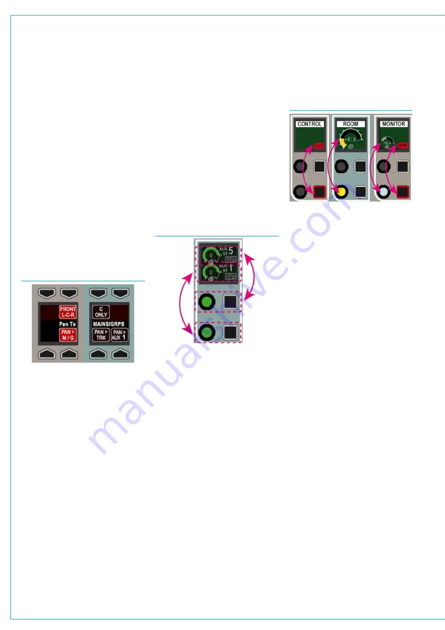
A button cell is shown in Fig 1 below.
Each graphic display is split into up to four
functions. Buttons above and below point
to the functions on the displays that they
control. Some functions are shown the
full width of the display. In these cases,
pressing either of the two buttons will
activate the function. A strip across the
centre of a button cell is sometimes used
as a label. Labels sometimes span across
more than one display and sometimes a
cell may have a label but no associated
button functions.
FIG 1 - BUTTON CELL EXAMPLES
Controlcell
The remaining area in the control bed is
made up of 16 control cells, demarcated
by white lines. Each control cell is made
up of a display, two rotary controls and
two buttons.
Control cell displays are generally split
with a function / parameter being
displayed in the top half, and a different
one being displayed in the bottom half.
The upper rotary control and button relate
to the upper half of the display, whilst the
lower rotary control and button relate to
the lower half of the display.
Depending on the panel mode and path
selected, some controls within a cell
and some cells as a whole may not have
a function. Active rotary controls are
illuminated. The illumination colour of
rotaries and buttons is dependent on the
function they control.
In Fig 2 an example from the O/P panel
mode, the lower rotary control adjusts the
Aux 1 output level, the lower button cuts
Aux 1 output. The upper controls have
the same functions but affect Aux 5.
FIG 2 - CONTROL CELL EXAMPLE
When faced with a control cell with
functions in the lower half only and a
blank upper half, it is a common mistake
for new users to attempt to use the upper
button / rotary. It is important to note that
the upper part of the display relates to
the upper rotary and button and that the
lower portion of the display relates to the
lower controls, even if the upper portion
of the display is not in use. One control
cell is unusual - the MON mode LS level
cell uses the full height of the display
to draw attention to it. In this case, the
lower rotary control is used to make the
adjustment. The upper rotary in this cell is
not used.
The example shown in Fig 3 above shows
three adjacent control cells from the
MON panel mode. The left hand display
shows the monitor LS cut status which
is activated by the bottom button in the
left hand control cell. The central display
is showing the monitor LS level which is
adjusted using the bottom rotary control
from that cell. The right hand display
shows the monitor LS dim level and
status, the bottom rotary and button in
this cell affect these controls. The other
4 buttons and rotaries in these three cells
have no function.
TFTtouchscreen
The third interface type in the modal panel
area is the upstand TFT touchscreen.
Various control parameters in the different
panel modes are changed using buttons
located on the TFT touchscreen.
If a touchscreen is found to be inaccurate,
it can be calibrated - Press the Tools
button in the right-hand button-cell of the
modes row. This replaces the fader layer
select buttons with setup functions. Press
the Misc button, then select CAL TFT
from the row of button cells above.
From a normal seating position, press
the TFT touchscreen in the centre of
the targets presented. Once complete,
change the panel mode to refresh the
display.
FIG 3 PART-USE CONTROL CELLS
SURFACE CONTROL OVERVIEW
Содержание Artemis
Страница 7: ...calrec com Putting Sound in the Picture ARTEMIS INFORMATION ...
Страница 11: ...calrec com Putting Sound in the Picture ARTEMIS INTRODUCTION ...
Страница 17: ...calrec com Putting Sound in the Picture ARTEMIS CONTROL OVERVIEW ...
Страница 29: ...calrec com Putting Sound in the Picture ARTEMIS CONTROL PANEL MODES ...
Страница 36: ...36 ARTEMIS Digital Broadcast Production Console Control Panel Modes WILDABLE CONTROLS ...
Страница 39: ...calrec com Putting Sound in the Picture ARTEMIS GETTING SIGNALS INTO ARTEMIS ...
Страница 69: ...calrec com Putting Sound in the Picture ARTEMIS PROCESSING AUDIO ...
Страница 93: ...calrec com Putting Sound in the Picture ARTEMIS ROUTING AUDIO ...
Страница 109: ...calrec com Putting Sound in the Picture ARTEMIS PASSING SIGNALS OUT OF ARTEMIS ...
Страница 117: ...calrec com Putting Sound in the Picture ARTEMIS MONITORING ...
Страница 132: ...132 ARTEMIS Digital Broadcast Production Console Monitoring ...
Страница 133: ...calrec com Putting Sound in the Picture ARTEMIS COMMUNICATIONS ...
Страница 138: ...138 ARTEMIS Digital Broadcast Production Console ...
Страница 139: ...calrec com Putting Sound in the Picture ARTEMIS METERING ...
Страница 148: ...148 ARTEMIS Digital Broadcast Production Console ...
Страница 149: ...calrec com Putting Sound in the Picture ARTEMIS SHOWS MEMORIES AND PRESETS ...
Страница 163: ...calrec com Putting Sound in the Picture ARTEMIS CONSOLE FACILITIES ...
Страница 168: ...168 ARTEMIS Digital Broadcast Production Console ...
Страница 169: ...calrec com Putting Sound in the Picture ARTEMIS EXTERNAL INTERFACING ...
Страница 180: ...180 ARTEMIS Digital Broadcast Production Console External Interfacing ...
Страница 181: ...calrec com Putting Sound in the Picture ARTEMIS SYSTEM STATUS ...
Страница 184: ...184 ARTEMIS Digital Broadcast Production Console ...
Страница 185: ...calrec com Putting Sound in the Picture ARTEMIS GLOSSARY OF TERMINOLOGY ...
Страница 191: ...calrec com Putting Sound in the Picture ARTEMIS FEATURES BY SOFTWARE VERSION ...


