background image

Paragon-X Getting Started Guide


Page 19 of 28


Paragon-X Constant Time Error (cTE) measurement 

This  section  details  how  to  perform  a  Time  Error  test.  This  requires  Paragon-X  to  have  Opt.  250 

(Master/Slave Emulation End to End) or Opt. 252 (Master/Slave Emulation Peer to Peer) fitted.  

1.


In Operating Mode, select 1588v2 and tick the Enable Master/Slave Emulation box.   

2.


On the Setup Interface screen, configure the ethernet interface to match the device under test 
e.g. 1GbE optical*.  
  

3.


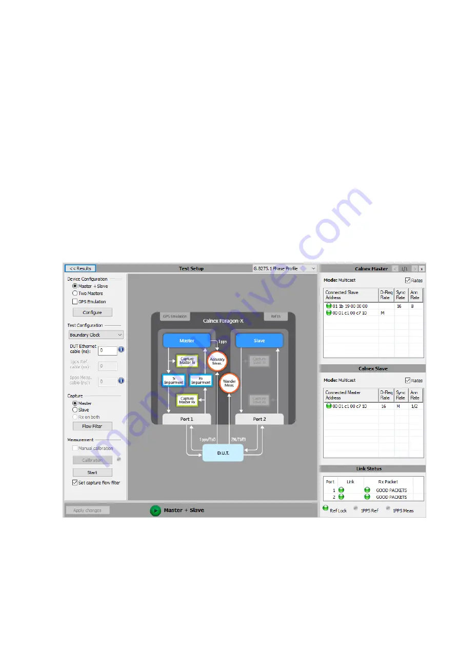
Click the Master/Slave Emulation button on the main GUI then configure for the device under 
test  e.g.  select  Boundary  Clock  in  the  Test  Configuration  dropdown  menu.  Select  a  suitable 
profile from the dropdown menu above the test set-up graphic, or use the Configure button to 
access manual settings. Note that the displayed image will change depending on which type of 
test  has  been  selected  and  so  provides  a  convenient  checkpoint  for  device  connectivity 
requirement. 
  

4.


Press the Start button in the Measurement section. This will start master-slave emulation, set up 
the appropriate capture filters, and start a capture.  

Note: when configured to use 100M line rate, instead of using the Start button, first enable the 
required PTP filters by using Capture > Flow Filter menu option then start MSE by using the 
green Slave button before starting capture. This allows Paragon-X to adjust for clock-
cycle offsets inherent at this rate.  


5.


Allow to run for 30s (or longer if desired).  

6.


Stop the capture by clicking the red Stop Capture button, then stop master-slave emulation by 
clicking the red Slave button at the bottom of the master-slave screen.  


Содержание Paragon-X

Страница 1: ...Paragon X Getting Started Guide Page 1 of 28...

Страница 2: ...rmance or use of this material To prevent fire or shock hazard do not expose the unit to rain or moisture To avoid electrical shock Use only power cord supplied or one with adequate ratings and connec...

Страница 3: ...eference Accessory 1pps ToD Frequency Converter Accessory Introduction For Next Gen technologies up to 10Gb s the Calnex Paragon X offers direct insight into actual device and service behaviour and th...

Страница 4: ...nex Solutions by telephone 44 0 1506 671 416 or by email support calnexsol com Paragon X AC adaptor 1 Power cord 1 USB memory stick 1 Getting Started Guide 1 Rb GPS External Reference AC adaptor 1 Pow...

Страница 5: ...D Frequency converter accessory to convert from high impedance single ended signal or RS 422 balanced signal Lower Front Aux Port earlier versions 10MHz Clock Out frequency locked to whatever referenc...

Страница 6: ...ter is enabled and generating packets all cases except Master Test configuration The 1PPS output is locked to whatever Paragon X 1PPS reference is in use pin 3 ve and pin 6 GND Both outputs use an in...

Страница 7: ...used for directly connecting Paragon X to a PC or laptop running Microsoft Windows 7 or Windows 10 OS the host PC Connection over a network is possible but not recommended see Calnex Application Note...

Страница 8: ...ower Input 11 Power Switch 12 1PPS Reference Input 13 Wander Measurement Inputs 14 Reference Inputs 15 Reset Switch 16 64K AMI Reference Input 17 GPS Reference 18 GPS Antenna Input 10 DC Power Input F...

Страница 9: ...64K AMI Reference Input For connection to 64kb s external system reference clock Pin 2 tip pin 6 ring pin 1 GND 17 GPS Reference An alternative to connector 12 accepts a 1PPS reference input signal on...

Страница 10: ...n AC outlet 4 Use Paragon X s rear panel power switch marked I 0 to switch on Paragon X 5 The blue display on the front panel will turn on Paragon X is initialised and ready to use after approximately...

Страница 11: ...gateway The IP address used should be different from the Paragon X IP address shown on its display only in the last 3 digits e g for a Paragon X IP address of 192 168 3 100 a suitable host PC IP addre...

Страница 12: ...to Paragon X or run the associated software first confirm that these ports are available Paragon X remote client application ports 9990 and 9000 CAT and PFV ports 1337 and 1338 If Paragon X is connect...

Страница 13: ...at the path may be different if the settings were changed from default during the installation process The software version of the Paragon X application can be found by clicking on Help About Paragon...

Страница 14: ...o alarms red current alarm yellow historic alarm i e alarm has occurred within the current test duration grey not active in the current configuration Link indicates if there is a physical Ethernet con...

Страница 15: ...any provide access to functions also available via workflow buttons and icon menu bar items allowing alternative methods for controlling Paragon X depending on user preference 6 Mode Title Bar Identif...

Страница 16: ...modes will depend on the options fitted licenced on Paragon X CES Circuit Emulation Service for example CESoP SAToP TDMoIP Requires Option 202 1588v2 IEEE1588v2 advanced analysis features Enable Maste...

Страница 17: ...se the dialog box 7 The Configure Capture workflow button may then be used to configure detailed settings for the selected measurements 8 Click on Setup Interface to configure the ethernet interfaces...

Страница 18: ...filters for packet impairments and Set Capture for packet decode and measurement filter setting Note the Set impair option is only available in Master Slave Emulation mode when capturing on the Parago...

Страница 19: ...aphic or use the Configure button to access manual settings Note that the displayed image will change depending on which type of test has been selected and so provides a convenient checkpoint for devi...

Страница 20: ...test pre enabled for further information on any given metric including their meaning any relevant Standards and the maths used in their calculation select the icon beside its entry 9 The View Results...

Страница 21: ...nd or the 10M Ref Output to the Paragon X 10MHz Reference Input rear panel connector The Rb GPS Frequency Reference has the following front and rear panel features Power On LED Rb Locked LED Track Syn...

Страница 22: ...ial the GPS Antenna input is connected properly and safely to the GPS antenna The GPS antenna and associated cables require an EMP Protector to be fitted for safety reasons The EMP Protector should be...

Страница 23: ...indicates that the equipment should only be disposed of through an approved method At the end of life please dispose of the equipment through a recognized and approved scheme fulfilling the local env...

Страница 24: ...nal conversion from ToD RS232 signals ToD RS 232 signal on DB9 connector port 6 RJ 45 connector port 4 RS 422 1PPS TTL signal format converter RJ45 connector port 3 TTL high impedance RJ 45 connector...

Страница 25: ...etting Started Guide Page 25 of 28 1PPS ToD Frequency Converter Revision D The Calnex external 1pps ToD Frequency converter may be supplied as an option to the Paragon X Opt 133 or ordered separately...

Страница 26: ...either sinusoidal or square waveform The frequency output is 1 5V peak to peak square wave into 50 POWER GOOD The POWER GOOD LED is on when power is supplied to the device There is no power switch Po...

Страница 27: ...Paragon X Getting Started Guide Page 27 of 28 This page is intentionally blank...

Страница 28: ...Paragon X Getting Started Guide Page 28 of 28...

Отзывы: