Vertex – Caller ID for VoIP
The Vertex is compatible with any software designed to use CallerID.com’s analog products. It is configured via the
Ethernet "Management Port”. The serial port output is for software that does not accept Caller ID data via Ethernet.
•
The Vertex is designed to capture only standard, non-encrypted SIP (Session Initiation Protocol)
.
•
If you are using standard telephones, a CallerID.com analog device will be required, instead of the Vertex.
Determine Your Type of VoIP
Hosted VoIP The service provider performs all voice switching, routing, messages on hold, call queuing, and other
call functions. In some cases, the end user needs only to connect VoIP phones to their network. Any significant
programming and configuration is accomplished by the service provider. Most small businesses use Hosted VoIP.
Managed VoIP involves additional equipment on site that handles most of the VoIP switching, routing, and call
processing. If you have a Managed VoIP system, an IT or telephone professional would have installed it.
Basics
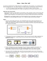
1. There are 3 network ports on the Vertex. The 2 VoIP Bridge Ports provide a pass-through link between two
network endpoints at 100BaseT, with processing circuitry in parallel. This approach allows passive packet
"sniffing" thus eliminating any network point-of-failure. The Management Port is the only port that presents itself
as an endpoint on the network.
2 The Management Port is used to configured the device. Data is sent out this port to software applications that
accept Caller ID via Ethernet. Connect this port to the same subnet that your Ethernet enabled Caller ID
application is running.
3. The two VoIP Bridge Ports are pass-through ports. They are not seen as endpoints by the network. They
simply connect the wire that carries all VoIP traffic between 2 endpoints such as a switch and a router.
All VoIP traffic of interest must pass through the VoIP Bridge Ports for correct Vertex operation.
4. We recommend the Vertex Bridge Ports connect the two network endpoints nearest to the VoIP telephones,
while still being in-line with all VoIP traffic. The diagram below shows the Vertex connecting a network switch to
a P.O.E. switch powering the phones.


