background image

en

9

5.5 

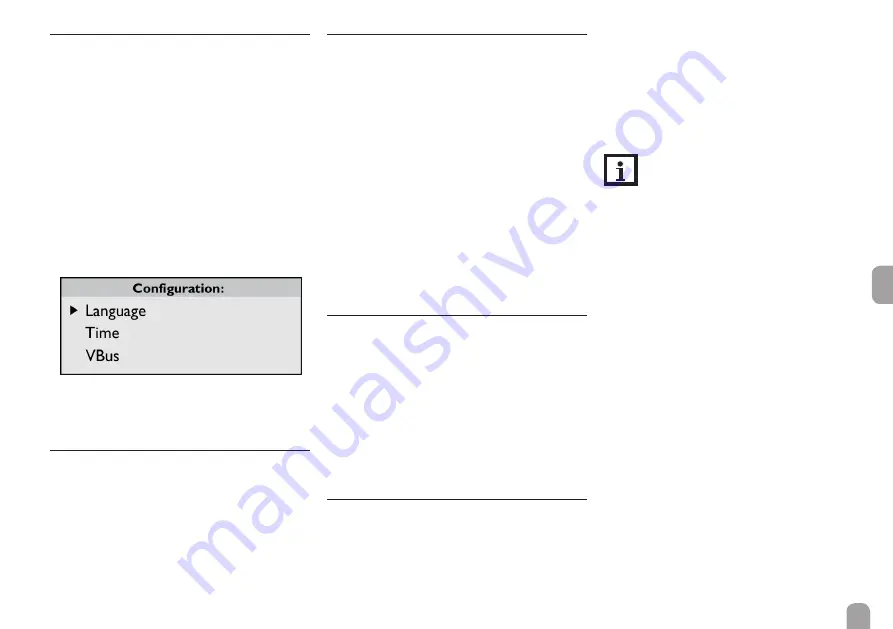
Configuration

In the Configuration menu, different adjustments 
can be made. 


Î

In order to access the menu, press button 3 for 
approx. 3 s.

Menu structure
The menu consists of the following sub-menus:
•  Language
•  Time
•  VBus
•  Sensors
•  Logging
•  Network
•  Erase
•  Version x.x


Î

In order to access the adjustment mode of a sub-
menu, select the desired sub-menu by pressing 
buttons 1 and 2, and confirm with button 3. 

5.5.1  Language

In the Language sub-menu, the menu language can 
be selected.


Î

Select the desired language by pressing buttons 
1 and 2.


Î

Briefly press button 3 to confirm the selection.


Î

In order to get back to the Configuration menu, 
select Back and confirm by pressing button 3.

5.5.2  Date and time

In the Time sub-menu, the date and time can be ad-
justed.


Î

To adjust the date, select the menu item Date in 
the Time sub-menu.


Î

Adjust the year by pressing buttons 1 and 2, and 
confirm with button 3.

Now the month is displayed, too. As soon as it has 
been adjusted and confirmed, the day appears as well.


Î

Adjust and confirm the current month and day as 
described above.


Î

To adjust the time, select the menu item Time in 
the Time sub-menu.


Î

Adjust the hours by pressing buttons 1 and 2, and 
confirm with button 3.


Î

Adjust the minutes by pressing buttons 1 and 2, 
and confirm with button 3.

5.5.3  VBus

In the VBus sub-menu, the monitoring of the VBus

®


connections can be activated.


Î

Select the desired VBus

®

 connection by pressing 

buttons 1 and 2, and confirm with button 3.


Î

To activate the monitoring of the VBus

®

 connec-

tion, select Yes. To deactivate the monitoring of 
the VBus

®

 connection, select No.

If an error occurs in a VBus

®

 connection, the operating 

control LED flashes and the message VBus (1 ... 6) 
no signal
 appears on the display.

5.5.4  Sensors

In the Sensors sub-menu, the sensor type and an off-
set can be adjusted for each sensor input.

Sensor type
For the sensor inputs S1 ... S3, the following sensor 
types are available: 
•  None
•  Pt1000
•  Pt500
•  Impulse
•  KTY

The selection Offset is not available when 
the sensor type Impulse has been selected.

In order to adjust the sensor type, proceed as follows:


Î

Select the desired sensor by pressing buttons 1 
and 2, and confirm with button 3.


Î

Select the menu item Type and confirm by press-
ing button 3.


Î

Select the right sensor type and confirm by press-
ing button 3.

If the sensor type Impulse has been selected, the 
impulse rate can be adjusted. In order to adjust the 
impulse rate, proceed as follows:


Î

Select the desired sensor by pressing buttons 1 
and 2, and confirm with button 3.


Î

In the corresponding sensor menu, select the 
menu item Vol./Imp.


Î

Adjust the desired value by pressing buttons 1 
and 2, and confirm with button 3.

Sensor offset
In order to adjust an offset for the sensor inputs S1 ... S3, 
proceed as follows:


Î

Select the desired sensor by pressing buttons 1 
and 2, and confirm with button 3.


Î

Select the menu item Offset and confirm by 
pressing button 3.


Î

Adjust the desired value by pressing buttons 1 
and 2, and confirm with button 3.

Содержание iSolar DL3

Страница 1: ...ank you for buying this product Please read this manual carefully to get the best performance from this unit Please keep this manual carefully Mounting Electrical connection Operating controls Manual...

Страница 2: ...o au thorised skilled personnel Only qualified electricians should carry out electrical works Description of symbols WARNING Warnings are indicated with a warn ing triangle They contain information on...

Страница 3: ...uts possible Current loop interface 0 4 20mA BACnet functionality for BACnet conform trans mission and reception of data Data logging onto SD card Technical data Housing plastic PC ABS and PMMA Protec...

Страница 4: ...urface such as a radiator or tap ATTENTION Short circuit A short circuit can lead to damage to electronic components Close the housing before establishing the mains con nection Initial installation mu...

Страница 5: ...losed wall plug and screw leav ing the head protruding Hang the housing from the upper fastening point and mark the lower fastening points centres 180 mm Drill 2 holes 6 mm and insert the wall plugs F...

Страница 6: ...minal block included and a common two wire cable VBus connection at the terminals 1 2 VBus connection 1 slave 3 4 VBus connection 2 slave 5 6 VBus connection 3 slave 7 8 VBus connection 4 slave 9 10 V...

Страница 7: ...nged in different ways An option can be selected by pressing buttons 1 and 2 and then confirming by pressing button 3 Now the option can be activated By pressing buttons 1 and 2 Yes can be selected to...

Страница 8: ...has been assigned to the DL3 the IP address and the house globe symbol appear as soon as the network cable has been connected 5 4 3 VBus display In the VBus display VBus information about the VBus de...

Страница 9: ...esired VBus connection by pressing buttons 1 and 2 and confirm with button 3 To activate the monitoring of the VBus connec tion select Yes To deactivate the monitoring of theVBus connection select No...

Страница 10: ...ging In the Logging sub menu the following adjustments can be made Interval Logging type SD card only if an SD card has been inserted into the SD card slot When Interval has been selected the logging...

Страница 11: ...lows Select the menu item Erase data by pressing buttons 1 and 2 and confirm with button 3 To erase all data confirm the security enquiry Erase by selecting Yes and confirming by press ing button 3 Th...

Страница 12: ...4 00 Recover Now Erase Erase data Yes No No Reset Yes No No Version 5 8 SD memory card slot SD memory card slot The SD memory card slot is located at the front of the device By means of the SD memory...

Страница 13: ...ogged data onto an SD memory card The data are stored as aVBus format file and can be read out on a computer using the ServiceCenter software 2 Export logged data onto a computer over the web interfac...

Страница 14: ...en 14 Note...

Страница 15: ...en 15 Note...

Страница 16: ...for the completeness of the drawings and texts of this manual they only represent some examples They can only be used at your own risk No liability is assumed for incorrect incomplete or false informa...

Отзывы: