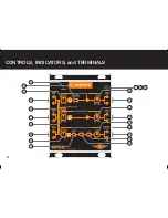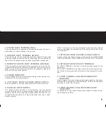
1. POWER INPUT TERMINAL (RED)
3. REMOTE TURN ON INPUT TERMINAL (ORANGE)
5. LEFT/RIGHT FRONT CHANNEL SIGNAL INPUTS
6. PARALLEL INPUT SWITCH
4. POWER INDICATOR
2. GROUND INPUT TERMINAL (BLACK)
8. LEFT/RIGHT MIXED IN/OUT TERMINALS
7. LEFT/RIGHT REAR CHANNEL SIGNAL INPUTS
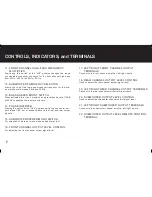
9. FRONT CHANNEL HIGH-PASS FREQUENCY
SELECTOR
10. REAR CHANNEL HIGH-PASS FREQUENCY
SELECTOR
This wire should be connected to the positive terminal of your ve-
hicle battery or other co12V source.
“OUT”: If the source unit has independent front and rear channel
outputs disengage the parallel input by sliding the switch to the
“out” position.
This wire should be connected the vehicle’s chassis. Ensure that
you have a good connection. When connecting the wire make sure
that there is no paint or other insulator blocking the connection.
AS INPUT TERMINAL: Connect to the subwoofer output of the
source unit.
AS OUTPUT TERMINAL: If running a multi cross-over system, con-
nect to the front channel input terminal of the next electronic cross-
over.
Connect to the rear channel output of the source unit. MAKE SURE
THAT THE PARALLEL INPUT SWITCH IS AT THE “OUT” POSITION!
Used to select the front channel high-pass crossover frequency
between 25Hz and 400Hz (or 500Hz and 8K Hz when its frequency
multiplier is in the “x20” position.
For selection of rear channel high-pass crossover frequency be-
tween 25Hz and 400Hz.
This wire should be connected to the remote turn on wire or anten-
na lead of the source unit. Should your system not have any turn on
leads, you can wire the remote terminal to an accessory lead which
turns on with your car’s ignition.
To be connected to the front channel output of the source unit.
“IN”: When the parallel input is in this position, the input signals
coming through the front channel signal inputs are split and di-
rected to the front rear channels simultaneously (this feature is to
be used when the source unit has no separate front, rear, or sub-
woofer outputs).
This LED lights up when the internal switching power supply is ac-
tivated and the unit is operational.
6
Содержание CXR-7
Страница 1: ...3 WAY ELECTRONIC CROSSOVER OWNERS MANUAL CXR 7 ...
Страница 2: ......
Страница 6: ...CONTROLS INDICATORS and TERMINALS 5 CXR 7 ...
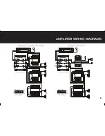
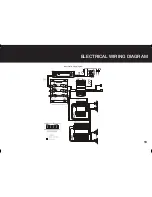
Страница 11: ...ELECTRICAL WIRING DIAGRAM 10 Electrical wiring diagram CXR 7 ...


