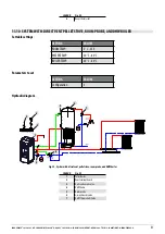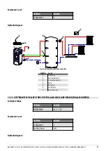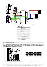
IDRO PRINCE
3
12-16-23-23 H
2
O - IDRO PRINCE 30-30 H
2
O - AQUOS
3
16-23-23 H
2
O - IDRON 16-22 AIRTIGHT - MIRA 16-22 - TESIS 16-23 AIRTIGHT - HIDROFIRE 22.8
63
14.7 DOOR CLOSING FUNCTIONALITY PERIODIC CHECK
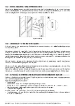
Check that door closing assures a correct seal (by means of the “paper sheet” test) and that when the door is closed, the closing
block (X in the figure) does not protrude from the sheet metal it is fixed to. In some products it will be required to remove the
aesthetic coating in order to evaluate any anomalous protrusion of the block with the door closed.
Fig. 68 - Door closing
14.8 SWITCHING OFF AT THE END OF THE SEASON
At the end of every season, before switching off the product, we recommend removing all the pellets from the hopper using a
vacuum with a long hose.
We recommend removing the unused pellets from the hopper because they can trap moisture. Disconnect any combustion air
ducts that can channel moisture into the combustion chamber, and above all, ask the specialised technician during the necessary
annual scheduled maintenance appointment at the end of the season to touch up the paint inside the combustion chamber with
specific silicone spray paints (that can be purchased at any retailer or customer service centre). This way, the paint will protect the
internal parts of the combustion chamber, preventing rust from forming.
When not in use, the appliance must be disconnected from the electrical mains. For greater safety, especially when there are
children, we recommend removing the power cable altogether.
When turning the stove back on, if the control panel display does not turn on when you press the main switch on the side of the
product, it means you may need to replace the service fuse.
There is a fuse holder compartment on the back of the product, under the power plug. After having disconnected the plug from
the mains, use a screwdriver to open the fuse holder compartment cover and, if necessary, replace the fuses (3.15 A time delay).
14.9 REPLACING THE OVERPRESSURE RELIEF VALVE FOR THE COMBUSTION CHAMBER
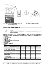
Combustion chamber overpressure rubber spacer “G” (fig.A) may become worn and/or damaged, thereby requiring replacement
once a year to ensure proper system operation.
Replace by following the instructions below:
• Remove the top
• Remove the first ceramic or steel side panel (depending on the type of stove)
• Unscrew the screw-washer-rubber spacer-roller shown in fig.A/C (on both sides of the cover). Then assemble the new kit:
• Align the screw-washer-rubber spacer-roller as shown in fig.C and screw it into the structure.
• Tighten the screw completely.
Now make sure that rubber spacer compression is correct, using the template supplied with the kit:
• Place the template on the cover (fig.B); the head of the screw must barely touch the upper reference. Otherwise, tighten or
loosen the screw until it does.


