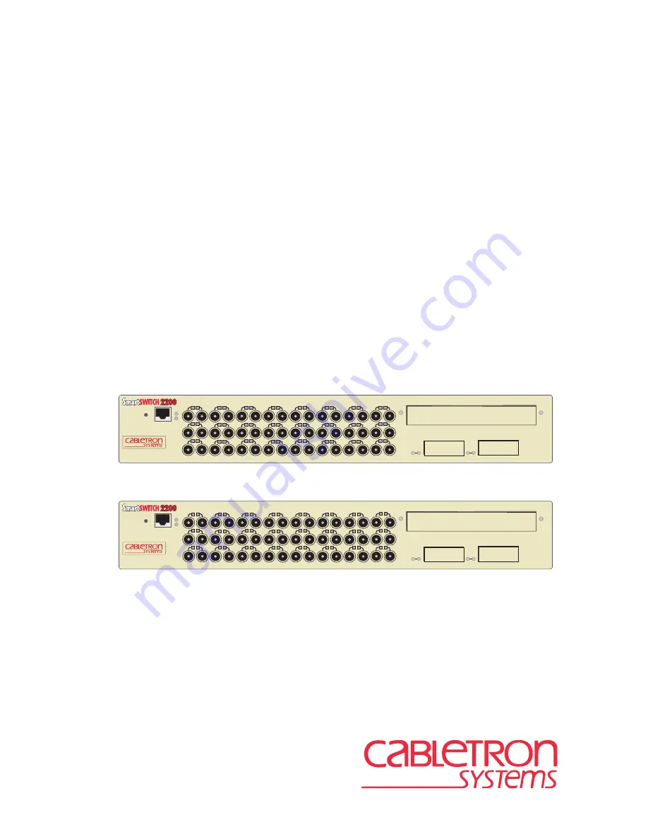
background image


9032314-04


2E48-27R/2E49-27R

SmartSwitch 2200

User’s Guide

COM

RESET

COM

RESET

RX

TX

RX

TX

24

RX

TX

8

RX

TX

16

RX

TX

23

RX

TX

7

RX

TX

15

RX

TX

22

RX

TX

6

RX

TX

14

RX

TX

21

RX

TX

5

RX

TX

13

RX

TX

20

RX

TX

4

RX

TX

12

RX

TX

19

RX

TX

3

RX

TX

11

RX

TX

18

RX

TX

2

10

17

RX

TX

1

RX

TX

9

RX

TX

RX

TX

RX

TX

24

RX

TX

8

RX

TX

16

RX

TX

23

RX

TX

7

RX

TX

15

RX

TX

22

RX

TX

6

RX

TX

14

RX

TX

21

RX

TX

5

RX

TX

13

RX

TX

20

RX

TX

4

RX

TX

12

RX

TX

19

RX

TX

3

RX

TX

11

RX

TX

18

RX

TX

2

10

17

RX

TX

1

RX

TX

9

RX

TX

2E48-27R

26

25

2E49-27R

26

25

PWR

CPU

PWR

CPU

Содержание 2E48-27R

Страница 1: ...21 RX TX 5 RX TX 13 RX TX 20 RX TX 4 RX TX 12 RX TX 19 RX TX 3 RX TX 11 RX TX 18 RX TX 2 10 17 RX TX 1 RX TX 9 RX TX RX TX RX TX 24 RX TX 8 RX TX 16 RX TX 23 RX TX 7 RX TX 15 RX TX 22 RX TX 6 RX TX 14...

Страница 2: ......

Страница 3: ...is manual may be trademarks or registered trademarks of their respective companies FCC NOTICE This device complies with Part 15 of the FCC rules Operation is subject to the following two conditions 1...

Страница 4: ...and Cabletron Systems Inc Cabletron that sets forth your rights and obligations with respect to the Cabletron software program the Program contained in this package The Program may be contained in fi...

Страница 5: ...DUCT EVEN IF CABLETRON HAS BEEN ADVISED OF THE POSSIBILITY OF SUCH DAMAGES BECAUSE SOME STATES DO NOT ALLOW THE EXCLUSION OR LIMITATION OF LIABILITY FOR CONSEQUENTIAL OR INCIDENTAL DAMAGES OR ON THE D...

Страница 6: ...CENELEC EN 60825 European Committee for Electrotechnical Standardization When operating within their performance limitations laser transceiver output meets the Class 1 accessible emission limit of al...

Страница 7: ...55022 EN 50082 1 EN 60950 Equipment Type Environment Networking Equipment for use in a Commercial or Light Industrial Environment We the undersigned hereby declare under our sole responsibility that...

Страница 8: ...Notice vi 2E48 27R 2E49 27R User s Guide...

Страница 9: ...lp 1 9 1 6 Related Manuals 1 10 CHAPTER 2 NETWORK REQUIREMENTS 2 1 SmartTrunk 2 1 2 2 10BASE F Network 2 1 2 3 FOIRL Fiber Optic Network 2 2 2 4 100BASE TX Network 2 2 2 5 100BASE FX Fiber Optic Netwo...

Страница 10: ...Configuration Menu Screen 5 14 5 7 General Configuration Screen 5 17 5 7 1 Setting the IP Address 5 20 5 7 2 Setting the Subnet Mask 5 21 5 7 3 Setting the Default Gateway 5 23 5 7 4 Setting the TFTP...

Страница 11: ...Download Using Runtime 5 59 5 17 Port Redirect Function Screen 5 60 5 17 1 Displaying the Source and Destination Entries 5 62 5 17 2 Changing Source and Destination Ports 5 63 5 18 Broadcast Suppressi...

Страница 12: ...1 FE 100TX B 1 B 1 1 Auto Negotiation B 2 B 2 FE 100FX B 3 B 3 FE 100F3 B 4 APPENDIX C OPTIONAL INSTALLATIONS AND MODE SWITCH BANK SETTINGS C 1 Required Tools C 2 C 2 Removing the Chassis Cover C 2 C...

Страница 13: ...organized as follows Chapter 1 Introduction outlines the contents of this manual and briefly describes the 2E4X 27R features Directions about how to obtain additional help and a list of related manua...

Страница 14: ...ork technology The 2E4X 27R can connect individual high bandwidth user devices such as workstations and provide a central switching point for multiple Ethernet segments built using devices such as Cab...

Страница 15: ...s 1 24 ST connectors Supports Multimode Fiber Optics Optional Fast Ethernet Interface Module Ports 25 and 26 COM Port System LEDs Port Status LEDs Network Ports 1 24 ST connectors Supports Single Mode...

Страница 16: ...ng technologies 1 3 2 Full Duplex Switched Ethernet Each switched Ethernet port supports full wire speed Ethernet communications and can be configured to operate in Full Duplex Switched Ethernet FDSE...

Страница 17: ...at an interval of 1 second The interval then doubles after every transmission until an interval of 300 seconds is reached At this point the interval remains at 300 seconds The RAD requests continue un...

Страница 18: ...with the IEEE 802 3u standard The 2E4X 27R provides IEEE 802 1D Spanning Tree Algorithm STA support to enhance the overall reliability of the network and protect against loop conditions The 2E4X 27R s...

Страница 19: ...net Interface Modules High Speed Interface Modules HSIMs are available from Cabletron Systems for additional connectivity to various networking technologies The HSIMs available for the 2E4X 27R are li...

Страница 20: ...that may be of special importance TIP Tip symbol Conveys helpful hints concerning procedures or actions CAUTION Caution symbol Contains information essential to avoid damage to the equipment Electric...

Страница 21: ...tron Systems products in the network A description of your network environment layout cable type etc Network load and frame size at the time of trouble if known The device history i e have you returne...

Страница 22: ...et Technology Guide Cabletron Systems Cabling Guide Cabletron Systems Port Based VLAN User s Guide Cabletron Systems SmartTrunk User s Guide These manuals can be obtained from the World Wide Web in Ad...

Страница 23: ...oduce poor network performance 2 1 SmartTrunk To connect the 2E4X 27R to a network so it can take advantage of the SmartTrunk feature there are certain rules concerning port connections and configurat...

Страница 24: ...ASE FX FIBER OPTIC NETWORK Ports 25 and 26 of the 2E4X 27R support the Cabletron Systems FE 100FX and FE 100F3 fiber optic interface modules The device at the other end of the fiber optic segment must...

Страница 25: ...tions listed below to correctly install the 2E4X 27R Unpacking the 2E4X 27R Section 3 1 Installing Options Section 3 2 Installing the 2E4X 27R on a shelf or tabletop or into a standard rack Section 3...

Страница 26: ...of damage Refer to Section 1 5 for details 3 2 INSTALLING OPTIONS If the 2E4X 27R is to be installed with an optional Fast Ethernet Interface Module refer to Appendix C for installation instructions...

Страница 27: ...ements listed in Appendix A In a shelf installation the shelf must support 13 6 kg 30 lb of static weight for each 2E4X 27R Maintain a temperature of between 5 C 41 F and 40 C 104 F at the installatio...

Страница 28: ...between 5 C 41 F and 40 C 104 F at the installation site with fluctuations of less than 10 C 18 F per hour CAUTION To ensure proper ventilation and prevent overheating leave a minimum clearance space...

Страница 29: ...R upside down as shown in Figure 3 2 on a clean flat surface Then attach the strain relief bracket to the bottom of the 2E4X 27R using the four 8 32 x 3 8 inch pan head screws Figure 3 2 Attaching the...

Страница 30: ...tion the 2E4X 27R between the vertical frame members of the 19 inch rack and fasten it securely with mounting screws as shown in Figure 3 4 Figure 3 4 Installing the 2E4X 27R in a Rack Screws 4 Rackmo...

Страница 31: ...LANVIEW LEDs After a successful boot the CPU LED turns ON green If the CPU LED is not green after one minute and turning amber there is no power redundancy Check the power cord connections and the pow...

Страница 32: ...n RJ45 connector for a twisted pair cable connection The FE 100FX and FE 100F3 have SC connectors for multimode and single mode fiber optic cable connections respectively To connect ST fiber optic cab...

Страница 33: ...ic ports on the applicable port on the module and from the ends of the connectors on each fiber strand 2 Refer to Figure 3 6 and attach one fiber to the applicable receive RX port on the 2E4X 27R Inse...

Страница 34: ...nt b Check the crossover of the cables Swap the cable connections if necessary c Check the cable for continuity d Check that the fiber optic connection meets the dB loss and cable specifications outli...

Страница 35: ...with Figure 3 7 FE 100TX Crossover Switch A schematic of a crossover cable is shown in Figure 3 8 If the wires do not cross over use the switch on the FE 100TX to internally cross over the RJ45 port F...

Страница 36: ...ications outlined in Section 2 4 e Confirm that the crossover switch is in the correct position If a link is not established contact the Cabletron Systems Global Call Center Refer to Section 1 5 for d...

Страница 37: ...00F3 uses Class 1 lasers Do not use optical instruments to view the laser output The use of optical instruments to view laser output increases eye hazard When viewing the output optical port power mus...

Страница 38: ...nnection meets the dB loss specifications outlined in Section 2 5 If a link has not been established contact the Cabletron Systems Global Call Center Refer to Section 1 5 for details 3 5 COMPLETING TH...

Страница 39: ...LANVIEW The LANVIEW LEDs Figure 4 1 allow quick observation of the network status to aid in diagnosing network problems Refer to Table 4 1 for a description of the LEDs For a functional description of...

Страница 40: ...e Cabletron Systems Global Call Center GCC Green Functional Power supply ies operating normally No action Amber Indicates loss of power supply redundancy 1 Ensure that the power cords are plugged in c...

Страница 41: ...indicating BPDUs being sent if STA is enabled and there is a valid link 1 Ensure that the STA is enabled and that there is a valid link 2 Contact the Cabletron Systems GCC for assistance Green Flashi...

Страница 42: ...LED and the Receive RX LED are shown in Figure 4 2 Table 4 2 and Table 4 3 provide a functional description of the 10 100 LED when the RX LED is on or off respectively Figure 4 2 RX and 10 100 LEDs N...

Страница 43: ...Off NOTE No link exists if the associated port 25 or 26 RX Receive LED is off LED Color Indication 10 100 Off No link or no cable attached FE 100TX forced to 10 Mbps operation or is manually set to a...

Страница 44: ...to Appendix A for proper console port pinouts Cannot contact the device from in band management Improper Community Names Table Refer to Chapter 5 for Community Names Table setup IP address not assign...

Страница 45: ...elease the RESET button The 2E4X 27R goes through a reset process for approximately 45 seconds Additional downtime may result as the device reenters the network CAUTION Pressing the RESET button reset...

Страница 46: ...Chapter 4 Troubleshooting 4 8 2E48 27R 2E49 27R User s Guide...

Страница 47: ...Assign IP address and subnet mask Select a default gateway Control access by establishing community names Download a new operation firmware image Designate which Network Management Workstations recei...

Страница 48: ...anges For example Press ESC twice means the ESC key must be pressed quickly two times SPACE Bar BACKSPACE Key These keys cycle through selections in some Local Management fields Use the SPACE bar to c...

Страница 49: ...access Local Management An IBM or compatible PC running a VT series emulation software package A Digital Equipment Corporation VT100 type terminal A VT type terminal running emulation programs for the...

Страница 50: ...lied in the kit to the COM port on the 2E4X 27R 2 Plug the RJ45 connector at the other end of the cable into the RJ45 to DB9 adapter supplied in the kit 3 Connect the RJ45 to DB9 adapter to the commun...

Страница 51: ...derline Cursor Style General Setup Menu Mode ID number Cursor Keys Power Supply VT100 7 Bit Controls VT100ID Normal Cursor Keys UPSS DEC Supplemental Communications Setup Menu Transmit Receive XOFF Bi...

Страница 52: ...ased node on the network Telnet connections to the 2E4X 27R require the community name passwords assigned at the SNMP Community Names screen of the 2E4X 27R For information about setting the IP addres...

Страница 53: ...in Figure 5 2 To connect the UPS device to the COM port of the 2E4X 27R proceed as follows 1 Connect the RJ45 connector at one end of the cable to the COM port on the 2E4X 27R 2 Plug the RJ45 connecto...

Страница 54: ...ps describe the procedure to access Local Management 1 Turn on the terminal Press ENTER this may take up to four times because the COM port of the 2E4X 27R auto senses the baud rate of the terminal un...

Страница 55: ...Figure 5 6 Refer to the appropriate figure that relates to the Operational Mode set for the device to see the applicable Local Management screen hierarchy NOTE The User s password is one of the commu...

Страница 56: ...Statistics Interface Statistics RMON Statistics SmartTrunk Configuration Ethernet Full Duplex Configuration General Configuration SNMP Community Names SNMP Traps Switch Configuration Device Menu Passw...

Страница 57: ...Using the Exit Command To exit LM using the EXIT screen command proceed as follows 1 Use the arrow keys to highlight the EXIT command at the bottom of the Local Management screen 2 Press ENTER The Loc...

Страница 58: ...cal Management hierarchy displays 3 Exit from Local Management by repeating steps 1 and 2 until the Device Menu screen displays 4 To end the LM session use the arrow keys to highlight the RETURN comma...

Страница 59: ...that are used to configure the 2E4X 27R and also provides access to the Device Specific Configuration Menu screen The Device Specific Configuration Menu screen provides access to the screens that all...

Страница 60: ...low the user to access and manage network devices Section 5 23 explains how to use the Network Tools utility 5 6 DEVICE CONFIGURATION MENU SCREEN The Device Configuration Menu screen Figure 5 8 provid...

Страница 61: ...he user to monitor and configure operating parameters for the 2E4X 27R For details refer to Section 5 7 SNMP COMMUNITY NAMES The SNMP Community Names screen allows the user to enter new change or revi...

Страница 62: ...plex Configuration screen allows each 10 Mbps port 1 to 24 to be set for either Standard Ethernet or Full Duplex operation The screen also indicates whether or not each port is linked to another Ether...

Страница 63: ...GENERAL CONFIGURATION menu item and press ENTER The General Configuration screen displays Figure 5 9 General Configuration Screen The following briefly explains each General Configuration screen field...

Страница 64: ...ress For details about how to change the subnet mask from its default value refer to Section 5 7 2 Default Gateway Modifiable Displays the default gateway for the 2E4X 27R This field is not defined un...

Страница 65: ...the 2E4X 27R so it operates as an IEEE 802 1D switch 802 1D SWITCHING option an IEEE 802 1Q switch 802 1Q SWITCHING option or as a Cabletron Systems SecureFast switch SECURE FAST VLAN option In 802 1D...

Страница 66: ...s For details refer to Section 5 7 11 IP Fragmentation Toggle Allows the user to enable or disable IP Fragmentation The default setting for this is field is ENABLED If the 2E4X 27R is to be bridged to...

Страница 67: ...If the management workstation that is to receive SNMP traps from the 2E4X 27R is located on a separate subnet the subnet mask for the 2E4X 27R may need to be changed from its default To change the sub...

Страница 68: ...urrent value but it does refresh the Subnet Mask field with the previous value 4 Use the arrow keys to highlight the SAVE command then press ENTER The warning screen shown in Figure 5 11 displays Figu...

Страница 69: ...field with the previous value 4 Use the arrow keys to highlight the SAVE command 5 Press ENTER The message SAVED OK displays at the top of the screen 5 7 4 Setting the TFTP Gateway IP Address If the n...

Страница 70: ...orm the following steps 1 Use the arrow keys to highlight the Device Date field 2 Enter the date in this format MM DD YYYY 3 Press ENTER to set the system calendar to the date in the input field NOTE...

Страница 71: ...the SAVE command at the bottom of the screen and press ENTER If the time entered is a valid format the message displays SAVED OK at the top of the screen If the entry is not valid Local Management do...

Страница 72: ...field 4 Use the arrow keys to highlight the SAVE command at the bottom of the screen and press ENTER If the time entered is within the 1 to 30 minutes range the message SAVED OK displays at the top of...

Страница 73: ...mode the module will reboot If the 2E4X 27R is set to 802 1Q SWITCHING refer to your Port Based VLAN User s Guide to configure the devices for this type of operation If the 2E4X 27R is set to SECURE...

Страница 74: ...address Refer to Section 5 7 1 Setting the IP Address Read this entire COM port configuration section before changing the settings of the COM port CAUTION Do NOT disable or alter the settings of the C...

Страница 75: ...t was DISABLED use the arrow keys to highlight SAVE at the bottom of the screen then press ENTER NOTE Exiting without saving causes the message NOT SAVED PRESS SAVE TO KEEP CHANGES to appear Exiting w...

Страница 76: ...R to accept the application 4 Use the arrow keys to highlight the SAVE command at the bottom of the screen then press the ENTER key The message SAVED OK displays indicating that the edits are saved Ta...

Страница 77: ...5 15 displays Figure 5 15 Clear NVRAM Warning Screen 5 Use the arrow keys to select YES and press ENTER The message CLEARING NVRAM REBOOT IN PROGRESS displays The 2E4X 27R clears NVRAM and reboots All...

Страница 78: ...tation field 2 Press the SPACE bar to choose either ENABLED or DISABLED 3 Use the arrow keys to highlight the SAVE command 4 Press ENTER The message SAVED OK displays at the top of the screen CAUTION...

Страница 79: ...es screen from the Device Configuration Menu screen use the arrow keys to highlight the SNMP COMMUNITY NAMES menu item and press ENTER The SNMP Community Names screen displays Figure 5 16 SNMP Communi...

Страница 80: ...me The available access levels are as follows read only This community name gives the user read only access to the 2E4X 27R MIB objects and excludes access to security protected fields of read write o...

Страница 81: ...sword in the field maximum 31 characters 3 Press ENTER 4 Repeat steps 1 through 3 to modify the other community names 5 Use the arrow keys to highlight the SAVE command at the bottom of the screen and...

Страница 82: ...plains each field of the SNMP Traps screen Trap Destination Modifiable Indicates the IP address of the workstation to receive trap alarms Up to eight different destinations can be defined Trap Communi...

Страница 83: ...ess ENTER If an invalid entry is entered the message INVALID IP ENTERED displays in the Event Message Line 4 Use the arrow keys to highlight the Trap Community Name field Enter the community name 5 Pr...

Страница 84: ...reen NOTE The Switch Configuration screen is not available if the operational mode of the device is set to SECURE FAST VLAN This screen may only be used when the device is configured to operate as an...

Страница 85: ...ts switch table before discarding it An address is automatically discarded when a valid frame is not received from that address within the time specified in the Age Time field To change the Age Time f...

Страница 86: ...us Toggle Allows the user to disable or enable a port by setting the status of the listed interface to either ENABLED or DISABLED To set the port status refer to Section 5 10 3 5 10 1 Setting the STA...

Страница 87: ...ult value being 300 seconds 3 Use the arrow keys to highlight the SAVE command at the bottom of the screen 4 Press ENTER The message SAVED OK is displays 5 10 3 Setting Enabling or Disabling the Port...

Страница 88: ...TER The Ethernet Full Duplex Configuration screen displays Figure 5 19 Ethernet Full Duplex Configuration Screen This section explains each field of the Full Duplex Configuration screen PORT Read only...

Страница 89: ...NK STATUS Read only Indicates whether there is a physical connection from this port to another 10BASE F device One of the following values displays Link There is a 10BASE F link signal present there i...

Страница 90: ...ports To set the Operation Mode for individual ports proceed as follows 1 Use the arrow keys to highlight the OPERATION MODE field adjacent to the number of the port s that you plan to change 2 Press...

Страница 91: ...vice Specific Configuration Menu screen displays Figure 5 20 Device Specific Configuration Menu Screen NOTE The PORT REDIRECT FUNCTION menu item on the Device Specific Configuration Menu screen may no...

Страница 92: ...file from a TFTP server to its FLASH memory For details refer to Section 5 16 PORT REDIRECT FUNCTION The Port Redirect Function screen allows the user to redirect traffic from one or multiple switch p...

Страница 93: ...the arrow keys to highlight the SYSTEM RESOURCES menu item and press ENTER The System Resources screen displays Figure 5 21 System Resources Screen The following briefly defines each field of the Sys...

Страница 94: ...ly being used Peak Switch Utilization Read only Shows the peak percentage of device switching capacity used since the last reset Reset Peak Switch Utilization Toggle Allows the user to reset the Peak...

Страница 95: ...nd press ENTER The High Speed Interface Configuration Menu screen displays Figure 5 22 High Speed Interface Configuration Menu Screen NOTE This screen does not display unless one or two Fast Ethernet...

Страница 96: ...e HSIM screens are described in their respective user s guides 5 15 HIGH SPEED INTERFACE CONFIGURATION SCREEN The High Speed Interface Configuration screen displays the types of interfaces installed i...

Страница 97: ...icates whether or not there is a physical connection from this port to another 10BASE T or 100BASE TX FX device One of the following values displays Link There is a link signal present and a valid phy...

Страница 98: ...when an FE 100FX or FE 100F3 is installed Section 5 15 1 describes how to configure a port with an FE 100FX or FE 100F3 If an FE 100TX is installed the field steps to Auto Negotiation 10Base T 10Base...

Страница 99: ...on 5 15 2 2 describes how to enable or disable advertised modes 5 15 1 Configuring an FE 100FX or FE 100F3 When an FE 100FX or FE 100F3 is installed in port 25 or 26 it must be manually set to operate...

Страница 100: ...field 2 Use the SPACE bar to select the desired mode Press ENTER If any mode other than Auto Negotiation is selected the port only operates in the chosen mode and Auto Negotiation is disabled 3 Use t...

Страница 101: ...SAVE command Press ENTER The message SAVED OK displays and Local Management saves the changes to memory 5 16 FLASH DOWNLOAD SCREEN The Flash Download screen shown in Figure 5 24 allows the user to re...

Страница 102: ...be downloaded If set for TFTP or RUNTIME the 2E4X 27R attempts a TFTP download based on the IP address and file name entered in the fields at the bottom of the Flash Download screen Section 5 16 1 de...

Страница 103: ...up the device boots from FLASH memory using the new image TFTP Gateway IP Addr Modifiable This field shows the IP address of the TFTP gateway server defined on the General Configuration screen in Sect...

Страница 104: ...event message line at the top of the screen and the new image is downloaded into FLASH memory 5 16 2 Image File Download Using TFTP To download a firmware image of FLASH to the 2E4X 27R using TFTP pr...

Страница 105: ...if you want the device to store the new image in FLASH memory until the device is reset or during the next power up 5 Use the arrow keys to highlight the TFTP Gateway IP Addr field 6 Set the IP addre...

Страница 106: ...lar port s where with the use of an analyzer or RMON probe all current traffic from the source port s can be examined To access the Port Redirect Function screen from the Device Specific Configuration...

Страница 107: ...configured ON to send errored frames to the destination ports or OFF to drop all errored frames and only forward traffic without errored frames to the destination ports Source Port n Selectable Allow...

Страница 108: ...on Entries There can be more than one Port Redirect Function screen depending on the number of port redirect entries Each screen displays up to 10 port redirect entries If there is more than one scree...

Страница 109: ...PACE bar to select either the ADD or DEL delete option Press ENTER This adds or deletes the port selections made in steps 2 and 4 and also updates the screen Source Port and Destination Port list 7 Us...

Страница 110: ...ssion screen Section 5 7 9 Setting the Operational Mode describes how to configure the device to operate in this mode Broadcast frames received above the threshold setting are dropped Firmware Revisio...

Страница 111: ...Time Since Peak field The Reset Peak field toggles between YES and NO For details refer to Section 5 18 1 1 12 or 13 24 Navigation Key When the Broadcast Suppression screen displays the current statis...

Страница 112: ...n 4 Press ENTER The message SAVED OK displays and the Time Since Peak field is also reset 5 19 DEVICE STATISTICS MENU SCREEN The Device Statistics Menu screen Figure 5 27 provides access to screens th...

Страница 113: ...INTERFACE STATISTICS The Interface Statistics screen provides the MIB II statistics for each switched interface on a interface by interface basis For details refer to Section 5 21 RMON STATISTICS The...

Страница 114: ...splays the following fields Port Read Only Identifies the interface or port number NOTE The Switch Statistics screen is not available if the operational mode of the device is set to SECURE FAST VLAN S...

Страница 115: ...reen displays the statistics are displayed for the first 12 ports These fields allow the user to step to a second or third screen for the same type of information for ports 13 through 24 or 25 through...

Страница 116: ...Ms gather their own statistics and may be viewed via the Local Management screens of the applicable HSIM Refer to your HSIM documentation for information on how to access these screens Firmware Revisi...

Страница 117: ...es and framing characters InUnicast Read Only The InUnicast field displays the total number of frames that have been received that were sent to a single address InNonUnicast Read Only This field displ...

Страница 118: ...that were discarded even though the frames contained no errors This field may increment because the switch needed to free up buffer space or the switch was being overutilized OutErrors Read Only This...

Страница 119: ...ield indicates whether the interface is operating in normal standard or full duplex mode This field displays either Standard or Full Duplex Interface nn Command This command is used to enter an interf...

Страница 120: ...nu screen and press ENTER The RMON Statistics screen displays Figure 5 30 RMON Statistics Screen NOTE The RMON Statistics screen provides statistics for all front panel Ethernet Interfaces and any Fas...

Страница 121: ...ex 4 Owner Read only This field displays the name of the entity that configured this entry Status Read only The Status field displays the current operating status of the displayed interface This field...

Страница 122: ...ad only The Oversized Pkts field displays the number of frames received whose size exceeded 1518 data bytes not including preamble but have a valid CRC Fragments Read only This field displays the numb...

Страница 123: ...aming bits but including FCS bytes 256 511 Octets Read only Displays the total number of frames including bad frames received that were between 256 and 511 bytes in length excluding framing bits but i...

Страница 124: ...he SPACE bar to increment or press the DEL delete key to decrement the index number 3 Press ENTER neither the RMON Index field nor the statistics will change until ENTER is pressed 5 22 2 Using the Cl...

Страница 125: ...Network Tools involves typing the command to be executed at the Network Tools prompt adding any desired or required extensions and pressing ENTER TIP Type help at the prompt to list all the commands...

Страница 126: ...resented in the following format command Syntax Shows the required command format It indicates where arguments if any must be specified Description Briefly describes the command and its uses Options L...

Страница 127: ...lists the network interface that the device is connected to the device s network address or IP address the device s physical address or MAC address and the media type of connection to the device Medi...

Страница 128: ...affect the bridging status of that interface while specifying ALL will affect every interface Options Not Applicable Example arp a Interface 30 30 30 30 Network Address 122 144 40 111 122 144 48 109...

Страница 129: ...ns Not Applicable Example netstat Syntax netstat option Description The netstat command provides a display of general network statistics for the managed device The netstat command must be used with on...

Страница 130: ...h restores the user configuration settings from NVRAM The user will be queried to confirm the reset command to ensure against unwanted resets netstat i Interface Description 1 ethernet csmacd 2 ethern...

Страница 131: ...e number of valid entries in the table will be displayed at the end of the table display Options Not Applicable Example NOTE The Network Tools connection to the device will be terminated upon executio...

Страница 132: ...ons Not Applicable Example soft_reset Syntax soft_reset Description This command restarts the software image which restores the user configuration settings from NVRAM The user will be queried to confi...

Страница 133: ...d telnet will attempt to contact the host at the default port Options Not Applicable Example link_trap Syntax link_trap enable disable status PORT all Description The link_trap command allows link tra...

Страница 134: ...d is only available if an HSIM A6DP is installed in the module e g 6E13X 25 This command allows the user to enable disable or check the current status of the Spanning Tree Algorithm on all ATM interfa...

Страница 135: ...uide 5 89 5 23 2 Special Commands done quit exit Syntax done quit or exit Description The done quit or exit command enables the user to exit from Network Tools and return to the Main Menu screen Optio...

Страница 136: ...Chapter 5 Local Management 5 90 2E48 27R 2E49 27R User s Guide...

Страница 137: ...e A 1 DEVICE SPECIFICATIONS A 2 PHYSICAL PROPERTIES A 3 ELECTRICAL SPECIFICATIONS Processor Intel i960 RISC processor Dynamic Random Access Memory DRAM 16 MB FLASH Memory 4 MB Dimensions 7 11H x 43 18...

Страница 138: ...hrough 24 Ethernet multimode fiber optic 802 3 10BASE F compliant with ST type connectors 2E49 27R Ports 1 through 24 Ethernet single mode fiber optic FOIRL compliant with ST type connectors Slots for...

Страница 139: ...electromagnetic compatibility EMC requirements Table A 1 COM Port Pin Assignments Pin Signal Name Input Output 1 Transmit Data XMT Output 2 Data Carrier Detect DCD Output 3 Data Set Ready DSR Input 4...

Страница 140: ...Appendix A Specifications A 4 2E48 27R 2E49 27R User s Guide...

Страница 141: ...h on the FE 100TX determines the crossover status of the cable pairs If the switch is on the X side the pairs are internally crossed over If the switch is on the side the pairs are not internally cros...

Страница 142: ...capabilities that can be reached between the two devices For example the Interface Module port adjusts to 100 Mbps when the device on the other end of the connection can also adjust between 10 Mbps o...

Страница 143: ...0 125 m fiber optic 6 0 dB 9 0 dB 62 5 125 m fiber optic 9 0 dB 12 0 dB 100 140 m fiber optic 15 0 dB 18 0 dB NOTE The transmitter power levels and receive sensitivity levels listed are peak power lev...

Страница 144: ...le Type Worst Case Budget Typical Budget 8 125 m fiber optic 10 0 dB 10 0 dB 12 5 125 m fiber optic 10 0 dB 10 0 dB NOTE The transmitter power levels and receive sensitivity levels listed are peak pow...

Страница 145: ...le This appendix covers the following items Required tools Section C 1 Removing the chassis cover Section C 2 Locations functions and settings for the mode switches Section C 2 1 Installing Optional F...

Страница 146: ...UNIT HAZARDOUS VOLTAGES ARE PRESENT AND COULD CAUSE PERSONAL INJURY AND OR DAMAGE THE UNIT DO NOT POWER UP THE 2E4X 27R AGAIN UNTIL THE COVER AND SCREWS ARE IN PLACE DECKEL VON DAS 2E4X 27R NICHT ABZ...

Страница 147: ...NG TO AVOID ELECTRIC SHOCK VORSICHT DIESES GER T HAT MEHR ALS EINEN NETZANSCHLU TRENNEN SIE VOR WARTUNGSARBEITEN DIE 2 NET ZANSCHL SSE VOM NETZ UM ELEKTRISCHE SCHL GE ZU VERMEIDEN ATTENTION CET APPARE...

Страница 148: ...ion of the mode switches and the switch settings for normal operation These switches are set at the factory and do not need to be changed Switch definitions and positions are as follows Switches 1 thr...

Страница 149: ...ile location from the BootP server and uses TFTP to download the image from the TFTP server If one of these requirements is not met the 2E4X 27R continues to request either the BootP server or the TFT...

Страница 150: ...s you can either use the factory default settings or reenter your own parameters Switch 8 Reset Password Community Names Changing the position of this switch clears user entered passwords stored in NV...

Страница 151: ...and 26 and the High Speed Interface Module for port 27 Figure C 3 Fast Ethernet Interface Module Connector Location 23141 11 Optional Fast Ethernet Interface Modules Connectors FRONT PANEL TOP VIEWS...

Страница 152: ...es are in the associated user s guide CAUTION The FE 100F3 uses Class 1 lasers Do not use optical instruments to view the laser output The use of optical instruments to view laser output increases eye...

Страница 153: ...ernet Interface Modules to be aligned over the connector CAUTION When installing an FE 100FX or FE 100F3 module into the 2E4X 27R remove the rubber plug on the module before proceeding CAUTION In the...

Страница 154: ...the Fast Ethernet Interface Module 5 Press down firmly on the Fast Ethernet Interface Module until the pins slide all the way into the motherboard connector Ensure that the Fast Ethernet Interface Mod...

Страница 155: ...old 5 65 time since peak 5 65 total RX 5 65 Built in Commands use of 5 80 C Cable specifications 100BASE F network 2 1 2 2 100BASE FX MMF 2 2 100BASE TX network 2 2 Chassis cover removal of C 2 COM po...

Страница 156: ...5 25 subnet mask 5 18 5 21 Getting help instructions for H Help related manuals 1 10 Hierarchy 802 1D switching mode 5 10 802 1Q switching mode 5 10 SecureFast VLAN mode 5 11 High Speed Configuration...

Страница 157: ...N Port Redirect Function screen destination port 5 62 source port 5 61 Navigating screens 5 9 Network connection FE 100FX FE 100F3 3 12 FX 100TX 3 10 Network connections 3 8 Network Tools built in com...

Страница 158: ...atistics Menu screen 5 66 Ethernet Full Duplex Configuration screen 5 42 exiting from 5 11 FLASH Download screen 5 55 General Configuration screen 5 17 hierarchy of 5 9 High Speed Interface Configurat...

Страница 159: ...Statistics screen 5 68 clearing counters 5 69 frames fltrd 5 69 frames frwded 5 69 frames rcvd 5 69 frames txmtd 5 69 interface 5 68 System Resources screen CPU type 5 47 current switch utilization 5...

Страница 160: ...Index Index 6 2E48 27R 2E49 27R User s Guide V VLAN configuration of 5 46...

Отзывы: