background image

19

5 Maintenance

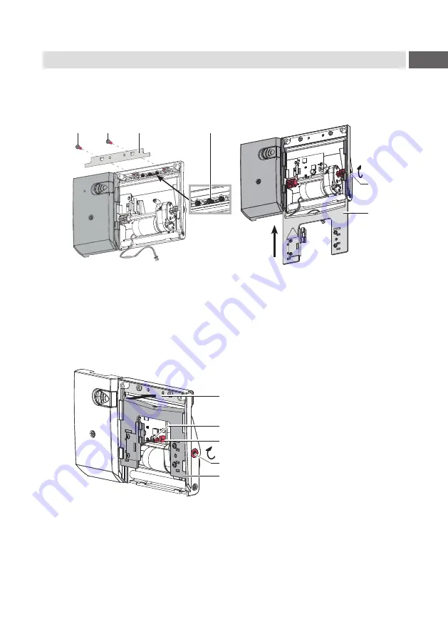
5.3  Reassembling the blades

The assembly of the cleaned or new blades and the assembly of the cutter is 
carried out in the reverse order of disassembly.

1

1

2

3

4

5


1.  Put the upper blade(2) on to the holders and make sure that the springs 

(3) are not be bent and remain in the guides.

2.  Fix the upper blade (2) with the screws (1).

3.  Push the lower blade (5) in the guides upward until the toothed rail on the 

upper blade (5) pushes against the gear wheels on the axle (4). 
Then turn the axle (4) clockwise with a 2.5 mm hex wrench and move the 
lower blade (5) near to the upper blade (2).

4

5

6
7

2

4.  Press the upper blade (2) inwards and slide the lower blade (5) over the 

upper blade (2) by turning the axle (4) clockwise to the top.

5.  Insert the plug (6) of the motor cable into the socket (7).

6.  Mount the cover and attach the cutter to the printer.

After turning on the printer, the lower blade position will be synchronized.

Содержание PSQ 403

Страница 1: ...Instructions Perforation Cutter PSQ 403 MADE IN GERMANY...

Страница 2: ...Please check www cab de for the latest update Terms and conditions Deliveries and performances are effected under the General conditions of sale of cab Germany cab Produkttechnik GmbH Co KG Karlsruhe...

Страница 3: ...Cutter 10 2 4 Mounting Cutter Tray 11 3 Operation 12 3 1 Preparation 12 3 2 Standard Operation 14 4 Printer Configuration 15 5 Maintenance 17 5 1 Removing the Blades for Cleaning and Replacement 17 5...

Страница 4: ...m risk which if not avoided may result in death or serious injury Caution Draws attention to a danger with low risk which if not avoided may result in minor or moderate injury Attention Draws attentio...

Страница 5: ...current technological status and the recognized safety rules However danger to the life and limb of the user or third parties and or damage to the device and other tangible assets can arise during us...

Страница 6: ...e device can also endanger operational safety Always have service work done in a qualified workshop where the personnel have the technical knowledge and tools required to do the necessary work Warning...

Страница 7: ...300 Thickness up to mm 1 5 Cutting length from mm 10 Gap height up to mm 2 0 Cut frequency cuts min with material height 1 mm without backfeed 200 Monitoring End position of the blade not reached Bla...

Страница 8: ...3 4 X Loosen screw 2 and remove cover 1 X Loosen screws 4 and remove cover 3 Attention For cutter operation there has to be mounted a tear off plate or a dispense plate on the printer to lead the mat...

Страница 9: ...system 3 and the roller 2 must be removed from the printer 1 2 3 4 5 X Swing down the locking system 3 X Loosen screw 4 X Remove the locking system 3 from the axle 1 Warning Do not reach between the...

Страница 10: ...re mounting or removing the cutter 1 2 3 4 5 X Insert the pins 3 of the cutter 5 into the holes 1 of the printer X Press the cutter against the printer That way the plug of the cutter will be connecte...

Страница 11: ...tter tray box 3 with the fixing brackets into the recesses 1 on the mounted cutter 2 X Slide the divider 4 according to the label height into the corresponding groove in the cutter tray box This ensur...

Страница 12: ...ctions of the printer X Fold up and lock the cutter unit 2 X Activate the commands for perforation or cut off in the software For direct programming use the following commands C p Perforation command...

Страница 13: ...uch a software is not possible X Adapt the perforation level to the media For direct programming use the following command O Cn n Value between 0 0 and 10 0 i Note If the label software has no setting...

Страница 14: ...ization is not necessary when the printhead was not opened between print jobs even if the printer was powered off between print jobs X Send a print job All labels in the job will be printed without st...

Страница 15: ...he printer Cut Parameters X Start menu X Select Setup Cutting Parameter Meaning Default Device info Information to the device Software version counts of cuts and errors Calibrate device Calibration of...

Страница 16: ...X Select Setup Printing Parameter Meaning Default Backfeed Method for backfeeding the label medium Backfeeding is necessary in the cutting and peel off modes since a label is pushed out passed the fro...

Страница 17: ...r from the printer 1 1 3 2 2 Loosen screws 1 and remove cover 2 towards the front 3 Pull the plug 3 of the motor cable out of the socket 4 5 6 6 7 8 4 Turn the axle 4 counterclockwise using a 2 5mm he...

Страница 18: ...er Printer Instructions and the cutter blades For a perfect function of the cutter it is necessary to grease the blades and guides at selected areas after each cleaning and before installing new blade...

Страница 19: ...r blade 5 in the guides upward until the toothed rail on the upper blade 5 pushes against the gear wheels on the axle 4 Then turn the axle 4 clockwise with a 2 5 mm hex wrench and move the lower blade...

Страница 20: ...e cutter must be calibrated X Remove label material X Start menu X Select Setup Cutting Calibrate device X Press Continue to start the calibration process After a cutter movement the display shows Dev...

Страница 21: ...n contact service Cutter cover open Cover of cutter is not mounted X Mount the cover Device too hot Temperature of the cutter is not in the allowed range X Let cool down the cutter Media too thick The...

Страница 22: ...C NOTE This equipment has been tested and found to comply with the limits for a Class A digital device pursuant to Part 15 of the FCC Rules These limits are designed to provide reasonable protection a...

Отзывы: