background image

33

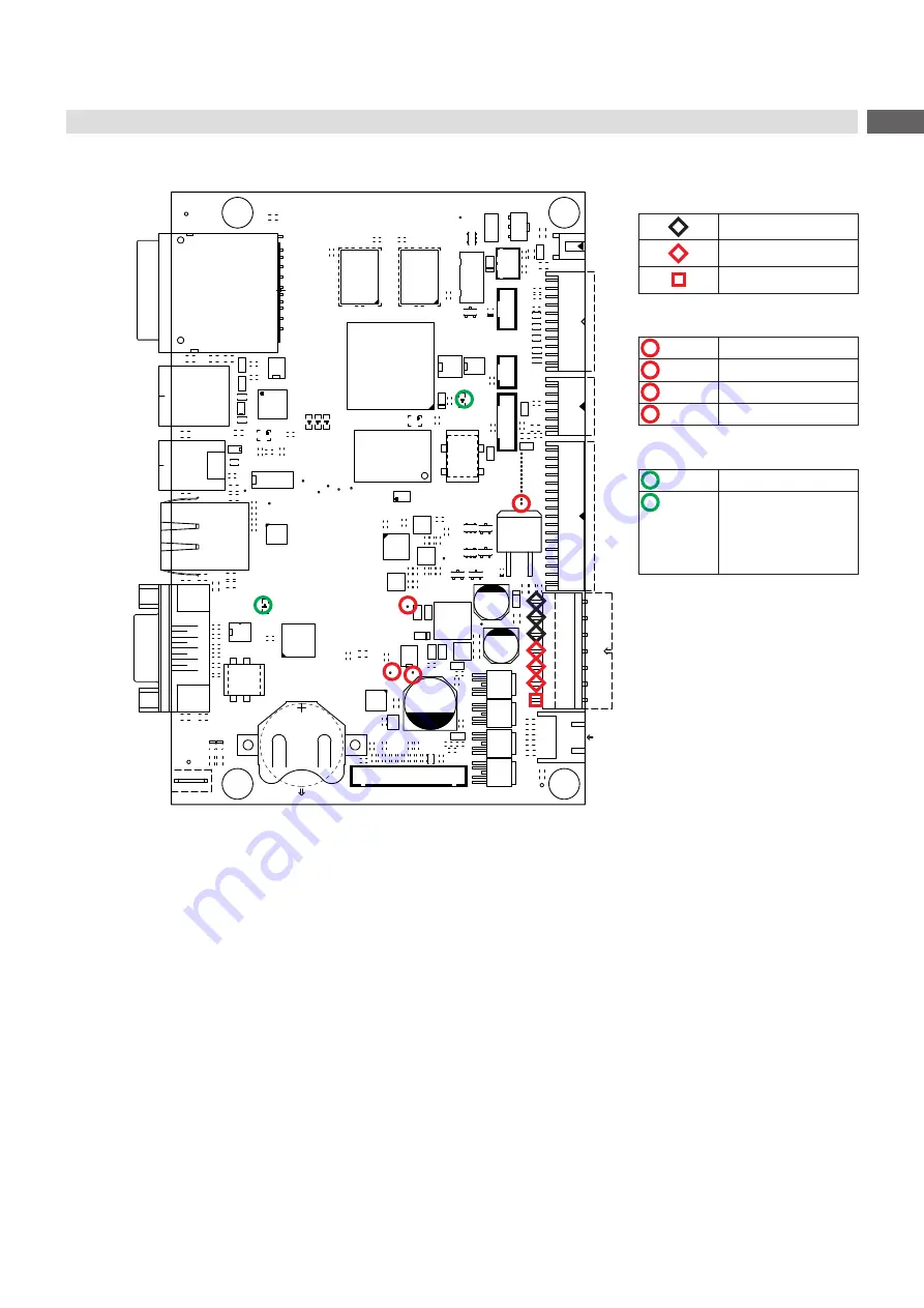
Layout Diagram PCB CPU

D4

V7

L5

C158

C159

C166

C167

C153

C154

C155

C156

C152

C161

C162

C163

C164

C160

C169

C170

C171

C172

C168

C175

C176

C177

C178

C174

C66

C112 C199

C258

C263 C265

C268

C207

C77

C157

C165

C173

C179

C206

2

4

1

3

G2

D13

V24

A

1

AE

25

E

K

B

C

D

F

G

H

J

L

M

N

P

R

T

U

V

W

Y

AA

AB

AC

AD

4

2

3

2

2

2

1

2

0

2

9

1

8

1

7

1

6

1

5

1

4

1

3

1

2

1

1

1

0

1 9 8 7 6 5 4 3 2

1

25 4

2

3

2

2

2

1

2

0

2

9

1

8

1

7

1

6

1

5

1

4

1

3

1

2

1

1

1

0

1 9 8 7 6 5 4 3 2

A

E

B

C

D

K

F

G

H

J

L

M

N

P

R

T

U

V

W

Y

AA

AB

AC

AE
AD

D1

R32

R34

R30

R1

R568

R4 R5

R19

R303

R68

R29

R96

1

1

1

R

7

9

R

R119

R120

R130

R131

R132

R61

R298

R70

R300

R268

C210

C212

C242

C15

C10

C11

C282

R62

R63

R64

R65

R73

R76

R100

R101

R270

R22

C286

L35

V14

L20

L21

L32

V2

C391

N1

62

R

32

R

V12

R33

C12

C13

L31

L34

L37

L38

C14

C16

C73

C192

C193

C194

C234

L42

R116

3

R

2

R

F2

L72

R59 R60

R84

R102

R121

R136

L26

1

N3

R150

R151

R152

R158

R159

C291

C292

U4

2

4

1

3

G6

R209

R213

R215

C246

C259

R123
R125

R71

V15

R166

1

U2

R219

R220

R160

R163

L27

R141

C219

R569 R570

R87 R88

R89

R169

V25

R171

R172

R304

R11

R21

R54

R55

L69

L70

L71

L74

L75

L83

L84

L85

R98

R99

R20

R25

R27

R36

R37

R323

V18

V19

V20

C113

F1

L30

R301

1

D14

1

D15

R254

L67

L68

C197

R117

N4

U8

R139

R227

R255

R236

R237

R280

1

#FD3

1

#FD1

1

#FD2

U3

C221

E1

R170

R168

R245

R247

R566

R567

1

Buchse

CON5

C275

A

1 2 3

7 8 9

B

C

D

E

F

G

H

J

K

L

M

N

P

R

T

D2

A

1 2 3

7 8 9

B

C

D

E

F

G

H

J

K

L

M

N

P

R

T

D3

V11

R299

C116

C148

C149

C184

R75

C187

R77

R78

C209

R85

A

1

14

B C D

E F G H J K L M N P

U7

R305

C237

C239

R155

C241

C245

X1

1bot

1top

CON3

1

CON4

R72

R74

R122

B5

B6

K

H1

K

H4

K

H5

K

H6

K

H7

C205

C255 C256

B1

B2

B3

B4

D5

P1

P2

CD

P3

P4

P5

P6

P7

P8

P9

GND

GND

WP

CON1

C307

C308

C42

R107

L29

L25

L80

L36

L43

L48

L49

L50

L1

L3

L6

L9

L10

L12

L15

L16

L17

L18

L2

L4

C260 C261

C313

C314 C320

R571

R572 R573 R574

R575

R108 R109

R294

R295

L64

R140 R142

+

C8

+

C6

R41

R42

R44

R45

V17

V1

N2

R47

R48

V3

R69

R56

R58

C267

R24

L87

L90

N6

C204

C114

2

1

CON10

2

1

CON11

2

1

CON12

1 CON17

1

CON9

1

2

CON7

1

CON16

1 CON15

1

CON14

1 CON13

+

C26

C27

C28

V9

V10

V13

V21

C288

A1

A2

K2

K1

1

Gn

Ye

CON2

1

CON8

U1

C232

C235

C240

C243

C252

V22

V23

R6

R40

1

CON18

R79

R80

V26

C196

C352

C283

C285

C3

C5

C1

C183

C180

C181

C182

C321

C150

C151

C222

C327

C4

C208

C211

C214

C215

C216

C217

C224

C223

C198C200

C201

C202

C203

C72

C9

C264

C272

C276
C279

C280

C269

C335

C338

C339

C340

C341

C293

C324

C342

C343 C344

C290 C295

C296

C297

C287

C299

C185

C186

C278

C300

C303

C301

C277

C270

C230

C231

C322

C323

C225

C325

C220

C302

C304

C271

C309

C310

C311

C312

C345

C346

C347

C349

C350

C2

C262 C266

C213

C289

C298

R126

R134

R137

R253

R256

R31

R35

L13

L93

L24

L28

L14

L23

L51

L52

L39

L66

L56

L57

L58

L40 L89

L59

L60

L61

L62

L63

L73

L53

C273

L33

R13

L7
L8

L11
L22

L91

L92

TOP4

TOP2

TOP3

TOP1

TOP26

TOP10

TOP9

TOP8

TOP25

TOP5

TOP6

TOP17

TOP18

TOP19

TOP20

TOP21

TOP22

TOP14

TOP13

TOP15

TOP16

TOP24

TOP23

TOP7

TOP12

TOP11

Measuring points at CON9:

GND

+24V

+V

MOT 

(+24V)

Measuring points on the PCB:

 TOP2

+24V

 TOP3

+5V

 TOP25

+24V TPH

 TOP26

+V

MOT 

(+24V)

LEDs on the PCB:

 H1

+3,3V

 H7

LED FPGA
on during start 
procedure 
blinking after start 
procedure

Figure 27 

Layout diagram PCB CPU X4.3

Содержание HERMES Q Series

Страница 1: ...Service Manual HERMES Q MADE IN GERMANY Label Printer ...

Страница 2: ...oducts discrepancies between documentation and product can occur Please check www cab de for the latest update Terms and conditions Deliveries and performances are effected under the General conditions of sale of cab Service Manual for the following products Germany cab Produkttechnik GmbH Co KG Karlsruhe Phone 49 721 6626 0 www cab de USA cab Technology Inc Chelmsford MA Phone 1 978 250 8321 www ...

Страница 3: ...16 5 1 2 Adjusting the Winding Torques 19 5 2 Adjusting the Brake at the Label Unwinder 20 5 3 Adjusting the Label Feed Path 21 5 4 Adjusting the Printing Mechanism 22 5 4 1 Preparing the Printer for Adjustment 22 5 4 2 Aligning the Printhead to the Print Roller 23 5 4 3 Adjusting the Printhead Pressure 24 5 4 4 Adjusting the Distance of the Printhead from the Paper Guiding Edge 25 5 4 5 Adjusting...

Страница 4: ...on Reference to section position illustration number or document Option accessories peripheral equipment special fittings Time Information in the display 1 2 General Safety Instructions This service manual is intended for use by qualified service and maintenance personnel For more operation and configuration information refer to the user or configuration manual Follow the general safety rules belo...

Страница 5: ...ing power units Working in the immediate vicinity of open power supply components Mechanical check of power supply components Modifying circuits in the device Test the zero potential of the device parts Check the working area for possible sources of danger such as wet floors defective extension cables defective protective conductor connections Additional precautions in the case of exposed voltages...

Страница 6: ...r brake adjustment at the label unwinder HERMES Qx xxx 2 cab Part No 5961092 Gauge for brake adjustment at the label unwinder HERMES Qx xxx 3 cab Part No 5961694 Standard tools Screw driver Torx size TX 10 TX 20 Allen key 1 5 mm Phillips head screwdriver size 1 Allen key 2 5 mm included Snap ring pliers ZGG 0 Snap ring pliers ZGG 1 Cylindrical dynamometer spring scale 0 10 N Cylindrical dynamomete...

Страница 7: ...er supply unit has discharged 1 2 4 5 6 3 7 Figure 1 Cleaning the label sensor 1 Remove the material from the printer 2 HERMES Q6 3 Remove the rear cover 3 HERMES Q6 3 Disconnect the plug 2 from the label sensor 1 4 Loosen the screw 5 5 Hold pressed the knob 4 and pull the label sensor with the handle 6 out of the profile HERMES Q6 3 That way the distance plate 7 is pushed out of label sensor guid...

Страница 8: ...ion 1 2 3 4 3 4 5 1 Data connector 2 Power connector 3 Threaded holes 4 Catching holes 5 Heating line Figure 2 Structure of the printhead Attention The printhead can be damaged by static electricity discharges and impacts X X Set up printer on a grounded conductive surface X X Ground your body e g by wearing a grounded wristband X X Do not touch contacts on the plug connections 1 2 X X Do not touc...

Страница 9: ...irst unplug the power cable 8 followed by the data cable 7 Mounting the Printhead 1 First connect the data cable 7 followed by the power cable 8 2 Place the printhead into the printhead assembly and insert the pins 9 into the holes 4 3 Press down the printhead carriage and fix the printhead with the screws 6 at the carriage using the threaded holes 3 4 Clean the heating line with the cleaning clot...

Страница 10: ...e 3 to the axle 1 Turn the roller to align it to the hexagonal end of the axle and push the roller further until it stops 5 Insert the ball bearing 5 in to the plate 3 and fix it with screw 6 Replacing the transport roller 1 Turn lever 10 clockwise to open the transport system 2 Loosen screw 11 3 Remove the transport roller 9 from the axle 8 4 Put the new roller onto the axle 8 Turn the roller eas...

Страница 11: ...t value of the torque cannot be set 5 1 on page 16 Removal and installation of the slipping clutch is also required for replacement of a winder 1 2 3 1 Internal rewinder coupling 2 Ribbon supply hub brake 3 Ribbon take up hub coupling Figure 5 Slipping clutches Danger Risk of death via electric shock X X Before opening the housing cover disconnect the device from the mains supply and wait at least...

Страница 12: ... 1 Pin 2 Spring 3 Winder axle 4 Tappet 5 Lever 6 Brake 7 Snap ring Figure 7 Brake at the ribbon unwinder 1 Unplug the printer from the electrical outlet 2 Remove the rear cover of the printer 3 Remove the snap ring 7 4 Pull the brake 6 from the winder axle 3 Ensure that the tappet 4 remains on the winder axle Reattach the tappet to the winder axle if it has been pulled off The axle profile is shap...

Страница 13: ...erial from the printer 2 Remove the rear cover 3 Disconnect the plug 2 from the label sensor 1 4 Loosen the screw 4 5 Hold pressed the knob 3 and pull the label sensor with the handle 5 out of the profile HERMES Q6 3 That way the distance plate 6 is pushed out of label sensor guide 6 Push the new label sensor into the guide until it stops HERMES Q6 3 Push the distance plate 6 into the guide of the...

Страница 14: ...um Configuration Manual 2 Unplug the printer from the electrical outlet 3 Detach all interface cables from the back of the printer 4 Remove all memory media from the slots 5 Dismount the rear cover 6 Unplug all plug connections 3 10 from the PCB CPU 2 7 Loosen screws 1 and remove PCB CPU 2 8 Attach the new PCB CPU 2 with four screws 1 9 Connect all cables to the PCB CPU 2 10 Mount the rear cover 1...

Страница 15: ... minute until the power supply unit has discharged 1 2 1 1 1 3 4 Figure 10 Replacing the power supply unit 1 Dismount the PCB CPU 4 5 on page 14 2 Unplug the cables from the connectors 3 4 3 Loosen 4 screws 1 and remove the power supply unit 2 4 Insert the new power supply unit an fix it with the screws 1 5 Connect the cables at the connectors 3 4 6 Re mount the PCB CPU 4 5 on page 14 7 Mount the ...

Страница 16: ...sum of the coupling torque and the torque of the brake Only the torque of the brake is measured when the winding axis is rotating counter clockwise For this reason measurement of the torques at the rewinders are required in both directions The method of measurement differs for the various types of slipping clutches Measurement of the winding torques at the transfer ribbon rewinder and unwinder pag...

Страница 17: ...he device from the mains supply and wait at least one minute until the power supply unit has discharged 1 Unplug the printer from the electrical outlet 2 Remove the rear cover 3 Remove the transfer ribbon from the printer 4 Attach the test collar 3 to the winder 4 5 Turn the knurled nut counterclockwise to clamp the test collar 6 Wind the cord attached to the test collar around the test collar sev...

Страница 18: ...he internal rewinder Danger Risk of death via electric shock X X Before opening the housing cover disconnect the device from the mains supply and wait at least one minute until the power supply unit has discharged 1 Unplug the printer from the electrical outlet 2 Remove the rear cover 3 Remove the labels from the printer 4 Push the cord 2 under a bracket 3 of the internal rewinder 4 and wind it ar...

Страница 19: ...least one minute until the power supply unit has discharged 2 1 Figure 13 Adjusting the winding torque 1 Unplug the printer from the electrical outlet 2 Remove the rear cover 3 Press the knurled ring 1 of the slipping clutch toward the housing wall The lock 2 of the knurled ring is released 4 Turn the knurled ring while pushing it and release it in the desired position 5 Ensure that the tabs of th...

Страница 20: ... blocked by the brake 4 Press down the swing arm so that the guide roller touches the lower end of the slot hole 2 Figure 14 right side Requirement B In that position the brake must unblock the label unwinder 6 7 10 11 12 4x 13 8 9 Figure 15 Adjusting the switching point of the brake If one of the requirements will not be achieved the switching point must be re adjusted 5 Turn the knurled knob 11 ...

Страница 21: ...ection of the material 2 run can be adjusted by the eccentric on the deflection roller 3 1 2 4 5 3 Figure 16 Adjusting the label feed path 1 Loosen the screw 4 2 Turn the eccentric on the 5 internal hexagon with the hexagon key in the right position 3 Hold the eccentric 5 and tighten the screw 4 with a second hexagon key 4 Check the label run If necessary adjust it again ...

Страница 22: ...ions Adjustment of the printing mechanism comprises the following procedures in the order specified 1 Preparing the printer for adjustment 5 4 1 on page 22 2 Aligning the printhead to the print roller 5 4 2 on page 23 3 Adjusting the printhead pressure 5 4 3 on page 24 4 Adjusting the distance of the printhead to the paper guiding edge 5 4 4 on page 25 5 Adjusting the transfer ribbon feed path 5 4...

Страница 23: ...sk of damage Attempting to adjust the printhead when the fixing screws 1 are tight can lead to defects at the printhead assembly X X Always loosen the fixing screws 1 before adjusting the printhead i Note X X Open and close the printhead after each step of the adjustment 1 Check the printhead alignment with the test function Test grid Configuration Manual or a similar pattern 2 If horizontal lines...

Страница 24: ...urn the adjustment screws 1a 1b counterclockwise until turning becomes perceptibly easy 2 Reduce the Heat level in the printer configuration until the print image is only barely recognizable Under these conditions inaccuracies become clearly visible during adjustment 3 Create print samples with the test function Test grid Configuration Manual or a similar print pattern 4 Adjust the adjustment scre...

Страница 25: ... guiding edge 1 Figure 20 Adjusting the distance of the printhead to the paper guiding edge 1 Print labels with vertical lines at a defined X position 2 Measure the distance of the vertical lines from the edge of the media Set value X 1 mm 3 If the measured value differs from the set value shift the printhead carriage by turning the screw 1 and repeat the measurement i Note The screw 1 is accessib...

Страница 26: ...n the print zone arising from the inner or outer side Bowing the printhead Avoiding wrinkles in the print zone arising from the middle Adjusting the front ribbon deflection Adapting the feed path to the print image Table 3 Adjusting the transfer ribbon feed path 2 1 Figure 21 Adjusting the transfer ribbon feed path 1 Adjusting the rear transfer ribbon deflection X X If the transfer ribbon drifts s...

Страница 27: ...X If the wrinkles cannot be remedied e g wrinkles in the center turn the adjustment screw 5 clockwise with extreme care using an Allen key 1 5 mm and observe the ribbon feed path When the adjustment screw 5 is tightened the printhead is bent downward slightly in the center It is possible that a slight lightening at the edge areas of the print image could occur here X X If bowing is not necessary t...

Страница 28: ...djusting the tension at the rewinder belt and the transport roller belt 1 Unplug the printer from the electrical outlet 2 Remove the rear cover 3 Adjusting the driver belt 1 for the rewinder Loosen the screws 3 4 Swing the bracket 2 so that the belt 1 is tensioned tightly Tighten the screws 3 4 If necessary further increase the tension 4 Adjusting the driver belt 5 for the transport roller Loosen ...

Страница 29: ...1 2 1 2 HERMES QL HERMES QR Figure 24 Checking the eccentrics position 1 Lock the printhead 2 Switch on the printer The ribbon saver will be synchronized After this the eccentrics are in the print position 3 Check the orientation of the eccentrics Attention Risk of ribbon saver malfunction In the print position the peak of the eccentric 2 at HERMES QL and at HERMES QR must point upwards and stand ...

Страница 30: ...supply and wait at least one minute until the power supply unit has discharged 1 2 3 4 Figure 25 Adjusting the magnetic clutch 1 Unplug the printer from the electrical outlet 2 Remove the rear cover 3 Loosen two screws 4 4 Pull armature disk 3 to the slipping clutch 5 Insert the distance caliber 0 1 mm 1 between armature disk 3 and chassis of magnetic clutch 2 6 Slide armature disk 3 to the chassi...

Страница 31: ...k the interface cable and replace it if necessary If all functionality of the interface has been lost replace the PCB CPU A peripheral device is not functioning Check whether the peripheral device is activated via programming Check the USB cable of the peripheral device and replace it if necessary Check the peripheral device Replace the PCB CPU Table 5 Failure of device functions 6 2 Permanent Har...

Страница 32: ...32 32 7 Block Diagram Figure 26 Block diagram HERMES Q ...

Страница 33: ... R85 A 1 14 B C D E F G H J K L M N P U7 R305 C237 C239 R155 C241 C245 X1 1bot 1top CON3 1 CON4 R72 R74 R122 B5 B6 K H1 K H4 K H5 K H6 K H7 C205 C255 C256 B1 B2 B3 B4 D5 P1 P2 CD P3 P4 P5 P6 P7 P8 P9 GND GND WP CON1 C307 C308 C42 R107 L29 L25 L80 L36 L43 L48 L49 L50 L1 L3 L6 L9 L10 L12 L15 L16 L17 L18 L2 L4 C260 C261 C313 C314 C320 R571 R572 R573 R574 R575 R108 R109 R294 R295 L64 R140 R142 C8 C6 R...

Страница 34: ...B CPU 33 M Magnetic clutch 30 Maintenance work 5 P PCB CPU replacement 14 Power supply replacement 15 Printhead position 23 Printhead pressure adjustment 24 Printhead replacement 8 Print image 22 Printing mechanism 22 Print roller replacement 10 Protective devices 5 R Rewinder 12 17 18 S Safety instructions 4 Slipping clutches Adjustment 19 Replacement 11 T Test collar 16 Torque 16 18 Transfer rib...

Отзывы: