background image

15

4.6 

Replacing the Label Sensor

i

Notice! 
Soiling of the label sensor can also cause malfunctions. 


Before replacing the label sensor, check whether it is soiled and clean it if necessary. 


3.2 on page 7

2

3

1

5

6

3

7

4

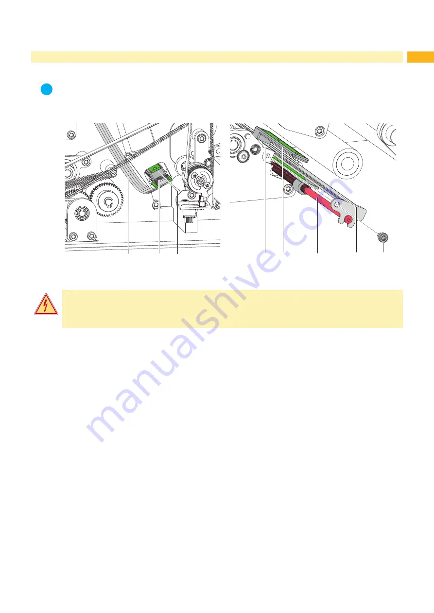
Figure 13  Replacing the label sensor

Danger!

Risk of death via electric shock!


Before opening the housing cover, disconnect the device from the mains supply and wait at least one 
minute until the power supply unit has discharged.

1.  Unplug the printer from the electrical outlet and remove the rear cover.

2.  Remove the material from the printer.

3.  Disconnect the plug (2) of the cable (1) from the connector of the label sensor (3).

4. 

Loosen the screw (7) and pull the label sensor (3) with the spindle (5) and the blind (6) out of the profile (4).

5.  Mount the new label sensor in the opposite order.

6.  Mount the rear cover and restore all connections.

7.  Adjust label sensor mechanically 

 Operator's Manual.

8.  Adjust label sensor electrically 

 Configuration Manual.

Replacing Assembly Units

Содержание Hermes C Series

Страница 1: ...Made in Germany Service Manual Hermes C Label Printer...

Страница 2: ...and product can occur Please check www cab de for the latest update Terms and conditions Deliveries and performances are effected under the General conditions of sale of cab Service Manual for the fo...

Страница 3: ...CB CPU 16 4 8 Replacing the Power Supply Unit 17 5 Adjustments 18 5 1 Measuring and Adjusting the Winding Torques 18 5 1 1 Measuring the Winding Torques 18 5 1 2 Adjusting the Winding Torques 21 5 2 A...

Страница 4: ...cting the environment Handling instructions Reference to chapter position picture number or document Option accessories peripherals extras Time Viewed in the display monitor 1 2 General Safety Instruc...

Страница 5: ...an emergency Disconnect the current supply before carrying out the following work Installing or removing power units Working in the immediate vicinity of open power supply components Mechanical check...

Страница 6: ...er 0 1 mm cab Part No 5961064 Gauge for brake adjustment at the label unwinder cab Part No 5961092 Standard tools Screw driver Torx size TX 10 TX 20 Allen key 1 5 mm Allen key 2 5 mm 200 mm shaft incl...

Страница 7: ...nplug the printer from the electrical outlet and remove the rear cover 2 Remove the material from the printer 3 Unplug the connector 2 of the cable 1 from the connector of the label sensor 3 4 Loosen...

Страница 8: ...inthead can be damaged by static electricity discharges and impacts X X Ground your body e g by wearing a grounded wristband X X Do not touch contacts on the plug connections 2 3 X X Do not touch prin...

Страница 9: ...13 through the holes in the adjusting elements 14 and the printhead retainer 10 into the drillings 15 of the new printhead 16 2 Ensure the correct positioning of the printhead 16 at the printhead reta...

Страница 10: ...erclockwise to lift the printhead assembly 2 Loosen screw 6 3 Remove ball bearing 5 and print roller 2 through the plate 3 4 Guide the new print roller through the plate 3 to the axle 1 Turn the rolle...

Страница 11: ...ransport rollers 1 Swing the locking system 4 away from the transport roller 2 2 Loosen the screw 3 3 Remove the transport roller 2 from the axle 1 4 Put the new roller onto the axle 1 Turn the roller...

Страница 12: ...nd installation of the slipping clutch is also required for replacement of a winder 2 3 4 5 1 1 Coupling internal rewinder 2 Coupling ribbon rewinder additional color 3 Coupling ribbon rewinder main c...

Страница 13: ...2 1 Pin 2 Lever 3 Spring 4 Winder axle 5 Tappet 6 Brake 7 Snap ring Figure 11 Brake at the ribbon unwinder 1 Unplug the printer from the electrical outlet 2 Remove the rear cover of the printer 3 Rem...

Страница 14: ...remove the wall spacer 7 3 Remove the snap ring 6 4 Pull the brake shoe 5 from the pin 3 remove the spring 4 from the brake shoe 5 Insert the spring in the new brake shoe 6 Push the brake shoe onto t...

Страница 15: ...st one minute until the power supply unit has discharged 1 Unplug the printer from the electrical outlet and remove the rear cover 2 Remove the material from the printer 3 Disconnect the plug 2 of the...

Страница 16: ...ews 2 and remove PCB CPU 1 8 Attach the new PCB CPU 1 with four screws 2 9 Connect all cables to the PCB CPU 1 10 Mount the rear cover 11 Restore all interface connections on the back of the printer 1...

Страница 17: ...printer from the electrical outlet 2 Remove the rear cover 3 Dismount the PCB CPU 4 7 on page 16 4 Unplug the cables from the connectors CN1 and CN2 5 Loosen 2 screws M4x10 3 and 2 screws M4x6 2 6 Rem...

Страница 18: ...The method of measurement differs for the various types of slipping clutches Measurement of the winding torques at the transfer ribbon rewinder and unwinder page 18 Measurement of the winding torque...

Страница 19: ...4 Attach the test collar 3 to the winder 4 5 Turn the knurled nut counterclockwise to clamp the test collar 6 Wind the cord attached to the test collar around the test collar several times 7 Secure sp...

Страница 20: ...ques at the internal rewinder Danger Risk of death via electric shock X X Before opening the housing cover disconnect the device from the mains supply and wait at least one minute until the power supp...

Страница 21: ...east one minute until the power supply unit has discharged 2 1 Figure 19 Adjusting the winding torque 1 Unplug the printer from the electrical outlet 2 Remove the rear cover 3 Press the knurled ring 1...

Страница 22: ...the guide roller 1 touches the lower end of the slot hole 2 Figure 20 right side Requirement B In that position the brake must release the label unwinder 12 4x 11 10 6 7 8 9 13 Figure 21 Adjusting the...

Страница 23: ...en X X The adjustment may only be done by trained and qualified electricians X X Do not touch the power supply area Principle of adjustment Remove the rear cover Loosen the screws 12 14 Turn eccentric...

Страница 24: ...es in the order specified 1 Prepare the label printer for adjustment 5 4 1 on page 24 2 Adjust the position of the printhead 5 4 2 on page 25 3 Adjust the printhead pressure 5 4 3 on page 26 4 Adjust...

Страница 25: ...zontal lines must be parallel to the label edge 2 If the printhead is not aligned properly loosen the screw 2 about one quarter turn 3 If the printhead is not aligned properly use the screws 1 to alig...

Страница 26: ...el is to be reduced in the printer configuration until the print image is only barely recognizable Under these conditions inaccuracies become clearly visible during adjustment 3 Create print samples w...

Страница 27: ...or outward turn the corresponding screw 3a or 3b clockwise in small increments Wait until the ribbon feed path has stabilized after each step of the adjustment 3 Check the ribbon feed path for wrinkl...

Страница 28: ...minute until the power supply unit has discharged Figure 29 Adjusting the belt tension i Notice The adjustment of all belt tension brackets can be done in the same manner 1 Unplug the printer from th...

Страница 29: ...e until the power supply unit has discharged 1 4 3 2 Figure 30 Adjusting the magnetic clutch i Notice The adjustment of both clutches can be done in the same manner 1 Unplug the printer from the elect...

Страница 30: ...a 4 5 6 1 3b 4 5 6 Ribbon saver additional color 1 4 3a 2 5 6 3b 4 5 6 1 Figure 31 Position of eccentrics and clock wheel in the saver phase Figure 32 Position of eccentrics and clock wheel in the pri...

Страница 31: ...ement points on the PCB CPU Figure 36 on page 35 No voltage at either measurement point The power supply unit may be defective Replace the power supply unit No voltage at one measurement point The PCB...

Страница 32: ...CB CPU VMOT Motor voltage is too low Check motor voltage 38 V at the measurement point Vmot Figure 36 on page 35 Voltage too low Replace the power supply unit Voltage is correct Replace the PCB CPU 24...

Страница 33: ...33 7 Block Diagram Figure 34 Block diagram Hermes C...

Страница 34: ...34 34 8 Layout Diagram CPU Figure 35 Layout diagram PCB CPU components side...

Страница 35: ...35 Figure 36 Layout diagram PCB CPU soldering side 8 Layout Diagram CPU...

Страница 36: ...23 Label sensor Cleaning 7 Replacement 15 M Magnetic clutch 29 P PCB CPU Layout diagram 34 Replacement 16 Power supply unit 17 Printhead Position 25 Pressure 26 Replacement 8 Printhead position 25 Pr...

Отзывы: