background image

16

16

In order to get the perfect label application it is necessary to set the jets of the applicator to the size and shape of the 
used label. 

Ideally the settings will have been set by the manufacturer with predetermined labeling material.

Should this not be possible the following steps will assist with the initiation and/or adjustments.

6.2 

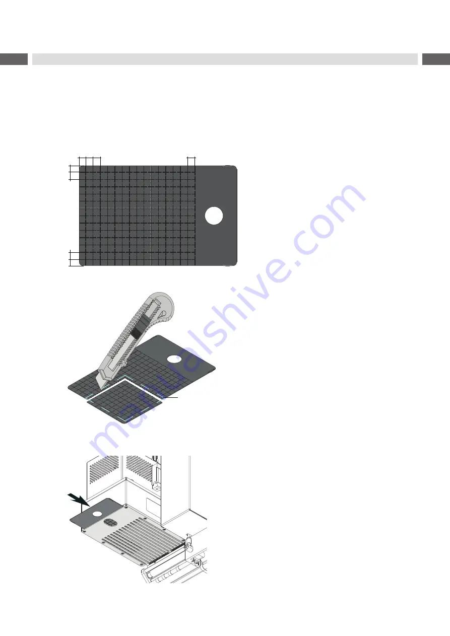
Sizing the Former Plate

Take a former plate from the accessories kit.

7   8   8

8


 8

8


 7

...

dimensions in mm

Fig. 13 

Former plate

Etikett

Fig. 14 

 Cutting the aperture

1.  Place the label on the former plate. Use the front 

and a side edge as orientation.

2.  Mark the label size on the on thefomer plate.

3.  Cut the next inside perforation.. 

 
The aperture must be smaller the the label.

Fig. 15 

Slide in the former plate

4.  Slide the former plate complete into the blow 

module. The aperture must be on the base plate 
side.

6 Operation

Содержание 6114 L

Страница 1: ...Assembly Instructions 6114 Made in Germany Air Jet Box ...

Страница 2: ...cumentation and product can occur Please check www cab de for the latest update Terms and conditions Deliveries and performances are effected under the General conditions of sale of cab Germany cab Produkttechnik GmbH Co KG Karlsruhe Phone 49 721 6626 0 www cab de USA cab Technology Inc Chelmsford MA Phone 1 978 250 8321 www cab de us Taiwan cab Technology Co Ltd Taipei Phone 886 02 8227 3966 www ...

Страница 3: ...Jet Module 10 4 2 Vacuum Adjustments 12 4 3 Adjusting the Blow Tube Supporting Air 13 4 4 Configuration Parameters of the Applicator 13 5 External Start Sensor 14 5 1 Connection 14 5 2 Signals 14 6 Operation 15 6 1 Standard Operation 15 6 2 Cleaning 15 6 3 Sizing the Former Plate 16 7 Error Messages 17 7 1 Error Messages of the Printer 17 7 2 Error messages of the Air Jet Box 17 8 Licences 18 8 1 ...

Страница 4: ... or third parties and or damage to the device and other tangible assets can arise during use The device may only be used for its intended purpose and if it is in perfect working order and it must be used with regard to safety and dangers as stated in the manual The device is designed to use on a cab printer of the HERMES Q and Hermes series Any other use or use going beyond this shall be regarded ...

Страница 5: ...n cause malfunctions Other unauthorized work on or modifications to the device can also endanger operational safety Always have service work done in a qualified workshop where the personnel have the technical knowledge and tools required to do the necessary work There are various warning stickers on the device They draw your attention to dangers Warning stickers must therefore not be removed as th...

Страница 6: ...ethod Air Jet Box 6114 L R Label width HERMES Q4 Hermes 42 mm 50 114 Label height2 mm 50 125 Product during labeling fixed in motion Labeling onto the product from the top sideways Product height variable Product distance to lower edge mm 200 Compressed air pressure bar 4 5 6 Cycle1 frequency min 120 Table1 Technical Data 1 Determined at 50 mm stroke below device smallest label height print speed ...

Страница 7: ...er 2 Setting screw for adjustment to the printer 3 Compressed air connector 4 Interface for external sensor 5 Base plate with the control unit 6 Blow nodule 7 Blow tube 8 Locking for hinges 9 SUB D 9 plug interface to the printer 10 Blow tube 11 Setting screw for fine adjustment height 12 Crossbeam 2 Product Description ...

Страница 8: ...umentation Fig 3 Contents of delivery i Note Please keep the original packaging in case the Air Jet Box must be returned Attention The device and printing materials will be damaged by moisture and wetness X X Only set up the label printer with the Air Jet Box in dry locations protected from moisture and water splashes ...

Страница 9: ...lves or other alignment elements This will enable use of the applicator directly after cleaning Mounting the applicator 1 Attach the applicator via the female part 1 of hinges to the male printer mounted hinges parts 2 2 Connect SUB D 15 male connector 6 to the female connector 7 of the printer 3 To secure the applicator slide the locking plate 3 under the hinge and tighten the screw 4 4 Swing the...

Страница 10: ... position of the dispensed labels relatively to the dispensing edge In the software an extra peel offset value is available The offset values from Peel position and from software are added together for execution Setting the Peel Position 0 0 mm Peel off offset in the software X X Check the setting in the software Perform labelling cycles by repeatedly pressing respectively Enter X X Adjust the pee...

Страница 11: ...tor pad edge and printer dispensing plate via the eccentric 5 6 By turning setting screw 6 the tamp assembly in a horizontal angle to the printer 7 By turning setting screw 1 the tamp assembly moves up or down Turn the screw until the dispensing plate and the suction plate are about 1 mm apart 1 mm 1 mm Fig 7 Adjusting the height of the air jet module ...

Страница 12: ...vers all the suction holes and is not hindered before it reaches its intended position on the suction plat 1 2 3 Fig 8 Vacuum adjustments X X Adjust the vacuum on the potentiometer vacuum 2 so that the label 3 will be sucked up over its entire area X X To increase the vacuum turn the potentiometer 1 counterclockwise to control the speed of the ventilator 1 ...

Страница 13: ... away from the dispense edge 6 Use the graduation guide for orientation 3 Open as many holes of the blow tube as are needed to cover the label width Remove rings 4 if necessary All holes outside the label width should be covered with the shrink tube rings provided Once the unneeded holes have been covered the shrink tube should be shrunk 4 Tighten screw 1 5 To increase the support air turn the set...

Страница 14: ...osition The signal START will transport and apply the label to the product In the application mode Apply Print the printing of the next label starts directly after application of the previous label In the application mode Print Apply the signal START must be sent for the print Pin Signal Name Description Activation active status without applicator with applicator 1 FSTLBL DREE Hermes Cycle sequenc...

Страница 15: ... carried out when the print job has been interrupted with the cancel key Synchronizing is not necessary when the print head was not lifted between print jobs This also applies if the printer was powered off between print jobs X X Start a print job X X Start the labelling process via PLC interface Error messages during labelling process are shown in the display of the printer Error Messages 6 1 Cle...

Страница 16: ...r adjustments 6 2 Sizing the Former Plate Take a former plate from the accessories kit 7 8 8 8 7 8 8 7 dimensions in mm Fig 13 Former plate Etikett Fig 14 Cutting the aperture 1 Place the label on the former plate Use the front and a side edge as orientation 2 Mark the label size on the on thefomer plate 3 Cut the next inside perforation The aperture must be smaller the the label Fig 15 Slide in t...

Страница 17: ...ressure to low 4 bar Pressure to high 6 bar Table4 Error messages of the Air Jet Box Error treatment X X Clear the error state X X In order to clear the error state press continue repeat or cancel Continue with the next label in the printing queue Repeat respectively the pause and enter key repeat the print of the label causing the error Only applicable with error Vac plate empty Cancel the curren...

Страница 18: ...id Device Air Jet Box Type 6114 Applied EC Regulations and Norms Directive 2006 42 EC on machinery EN ISO 12100 2010 EN ISO 13849 1 2015 EN 60950 1 2006 A11 2009 A12 2011 A1 2010 A2 2013 Person authorised to compile the technical file Erwin Fascher Am Unterwege 18 20 99610 Sömmerda Signed for and on behalf of the Manufacturer cab Produkttechnik Sömmerda Gesellschaft für Computer und Automationsbau...

Страница 19: ...gnated below this statement shall thereby be made invalid Device Air Jet Box Type 6114 Applied EU Regulations and Norms Applied Norms Directive 2014 30 EU relating to electromagnetic compatibility EN 55024 2010 EN 55032 2012 EN 61000 6 2 2005 Directive 2011 65 EU on the restriction of the use of certain hazardous substances in electrical and electronic equipment EN 50581 2012 Commission delegated ...

Отзывы: