50
50
9
Drawings
9.1
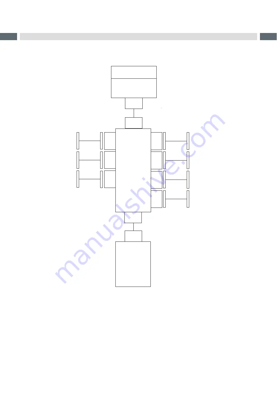
Block diagram
49
Applicator
interfaces
CON 2
CON 1
CON 3
CON 1
1
CON 12
36
Valve block
CON 1
58
Applicator control
CON 1
22
Sensor end position
cylinder (1) Z
51
Sensor start position
cylinder (1) Z
47
SUB-D 9
Interface to the printer
53
Sensor start position
cylinder flag
CON 21
CON 22
54
Sensor end position
cylinder flag
Fig. 54
Block diagram
57
EEPROM
55
Sensor
cylinder pliers
CON 31
CON 32
56
Sensor
cylinder peel position


