6
I. Main control cable and WMP-2100 configuration
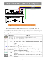
Wires configuration of WMP-2100 features color management, there are
seven different control cables to transmit signals. Every colored cable is designed
for a
unique function as shown below.
Color Abbreviation
Function
Yellow
RF OUT RF control signal cable: output signal to decoder
Red
B+ OUT DC 24V on WMP-60 Decoder
Black
GND
RF IN
、
RF OUT
、
B+ OUT
、
INTERCOM same ground wire signal
cable
Blue
RF IN(KEY)
Return signal cable
For example: N.O
、
N.C and self-detect
Purple
INTERCOM Intercom signal cable: need connect the signal wiper and
ground wire to control signal.
Green
COM
Power amplifier output AUX: No cathode or anode (No +/-
different)
White
100V
Power amplifier output AUX: No cathode or anode (No +/-
different)
GND
RF OUT
I.T
AMP COM
B+ DC 24V
RF OUT
POWER AMPLIFIER
POWER
AC
0FF
ON
AUTO FUSE
LEVEL
PL
PAB-5400
AUTO FUSE
DC
AMP 100V
黃色
紅色
黑色
藍色
紫色
綠色
白色
GND
RF OUT
I.T
AMP COM
B+ DC 24V
RF OUT
AMP 100V
黃色
紅色
黑色
藍色
紫色
綠色
白色
WMP-2100
Fig . 1 Connection structure between WMP-2100 and WMP-7C
Содержание WMP-2100
Страница 14: ...13 b WMP 60 200 zones DIP switch chart ...
Страница 23: ...22 X System Structure ...


