INSTRUCTION, USE AND
MAINTENANCE MANUAL
GB
Page 15 of 68
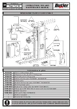
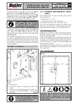
The use of the machine requires a usable space of
mm 5000x5000, (as indicated in
Fig. 11
). The use of
the machine must respect the shown distances. From
the control position the operator is able to observe all
the machine and surrounding area. He must prevent
unauthorized personnel or objects that could be dan-
gerous from entering the area.
The machine must be preferably used on an horizontal
floor. Avoid yielding or irregular surfaces.
The base floor must be able to support the loads
transmitted during operation. This surface must have
a capacity load of at least 500 kg/m².
The depth of the solid floor must be sufficient to guar-
antee that the support feet rest safely.
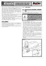
10.3 Lighting
The machine does not require its own lighting for
normal working operations. However, it must be used
in an adequately lit environment.
In case of poor lighting use lamps having total power
of 800/1200 Watt.
7503-M002-6_B
NAV26HW - NAV26HW.S - NAV26HW.ST
11.0 CONTROLS
11.1 Control device (NAV26HW - NAV26HW.
ST)
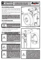
The control (handle control) can be moved according
to the positioning necessities of the operator.
MAKE SURE THERE ARE NO PER-
SONS OR OBJECTS HIDDEN TO
THE OPERATOR VISUAL FIELD
BY THE WHEEL SIDE PLAY (ESPE-
CIALLY IN CASE OF WHEELS WITH
LARGE DIMENSIONS).
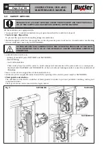
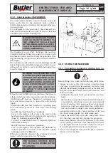
The control (
Fig. 12
) consists of:
•
“A” lower selector
(with guard) for wheel holder
mandrel open/close control with three positions:
one central position “stable” to stop mandrel open/
close movement and two positions “with maintained
control” to open/close mandrel jaws (NAV26HW);
•
“B” lever
for tool holder tool/bead breaking roll
translation control with three-positions: one central
position “stable” to stop translation and two positions
“with maintained control” for tool/bead breaking roll
support translation rightwards or leftwards (from
working position “C”
Fig. 11
);
•
“C” lever
three-positions control for vertical trans-
lation of mandrel arm: central “firm” position for
movement stop and two “hold activation” positions
for arm up and down translation;
•
“D” lever
control mandrel anticlockwise/clockwise
rotation.
Fig. 12


